Method for manufacturing electrode material and electrode material

a manufacturing method and electrode material technology, applied in the direction of contacts, air-break switches, transportation and packaging, etc., can solve the problems of lowering the packing percentage of the electrode material, the contact material cannot meet all of the above characteristics, and the dispersion of the packing percentag

Active Publication Date: 2019-11-26
MEIDENSHA ELECTRIC MFG CO LTD
View PDF11 Cites 0 Cited by
  • Summary
  • Abstract
  • Description
  • Claims
  • Application Information

AI Technical Summary

Benefits of technology

[0080]In the electrode material manufacture method of the present invention, the dispersion reaction of Cr and Mo (i.e., a heat-resistant element) at the primary sintering is suppressed, thereby decreasing vacancies and improving packing percentage. Therefore, it is considered that the advantageous effects of the present invention cannot be obtained in the case of using a perfect solid solution powder in which Mo is perfectly dissolved in Cr. However, in a solid solution between Mo powder and Cr powder, which are mixed together in a ratio such that Cr is greater than Mo by weight, it is not easy to make a perfect solid solution of Mo. Therefore, in the case of forming a MoCr solid solution by mixing Mo powder and Cr powder in a ratio such that Cr is greater than Mo by weight, the obtained MoCr solid solution powder is considered not be a perfect solid solution of Mo and Cr (other heat-resistant elements are also similar). For example, a perfect solid solution of Mo was not formed under the treatment condition of the baking step S2 of the electrode material of Example 1. Furthermore, in the case of increasing the proportion of Cr, a sintering reaction among Cr tends to occur at the preliminary sintering. Therefore, the formation of a perfect solid solution of Mo is considered to be difficult.
of the present invention cannot be obtained in the case of using a perfect solid solution powder in which Mo is perfectly dissolved in Cr. However, in a solid solution between Mo powder and Cr powder, which are mixed together in a ratio such that Cr is greater than Mo by weight, it is not easy to make a perfect solid solution of Mo. Therefore, in the case of forming a MoCr solid solution by mixing Mo powder and Cr powder in a ratio such that Cr is greater than Mo by weight, the obtained MoCr solid solution powder is considered not be a perfect solid solution of Mo and Cr (other heat-resistant elements are also similar). For example, a perfect solid solution of Mo was not formed under the treatment condition of the baking step S2 of the electrode material of

Problems solved by technology

Since some of these characteristics conflict with each other, there is no contact material satisfying all of the above characteristics.
However, in the sintering step of a MoCr fine dispersion electrode material containing a low melting metal added thereto, there was a risk that vacancies were generated in the electrode interior to result in lowering of packing percentage of the electrode material.
Furthermore, there was a risk that dispersion occurred in packing percentage by the temperature distribution of the sintering furnace.
If packing percentage of the electrode material lowers by the generation of vacancies in the electrode material, there is a risk that brazing material (e.g., Ag) is absorbed into vacancies of the electrode's inside in the brazing step to result in difficulty in brazing of the electrode material.

Method used


Image

  • Method for manufacturing electrode material and electrode material
  • Method for manufacturing electrode material and electrode material
  • Method for manufacturing electrode material and electrode material

Examples


example 1

[0061]The electrode material of Example 1 is an electrode material prepared by the same method as that of Comparative Example 1, except that the sintering temperature in the primary sintering step S6 was different.

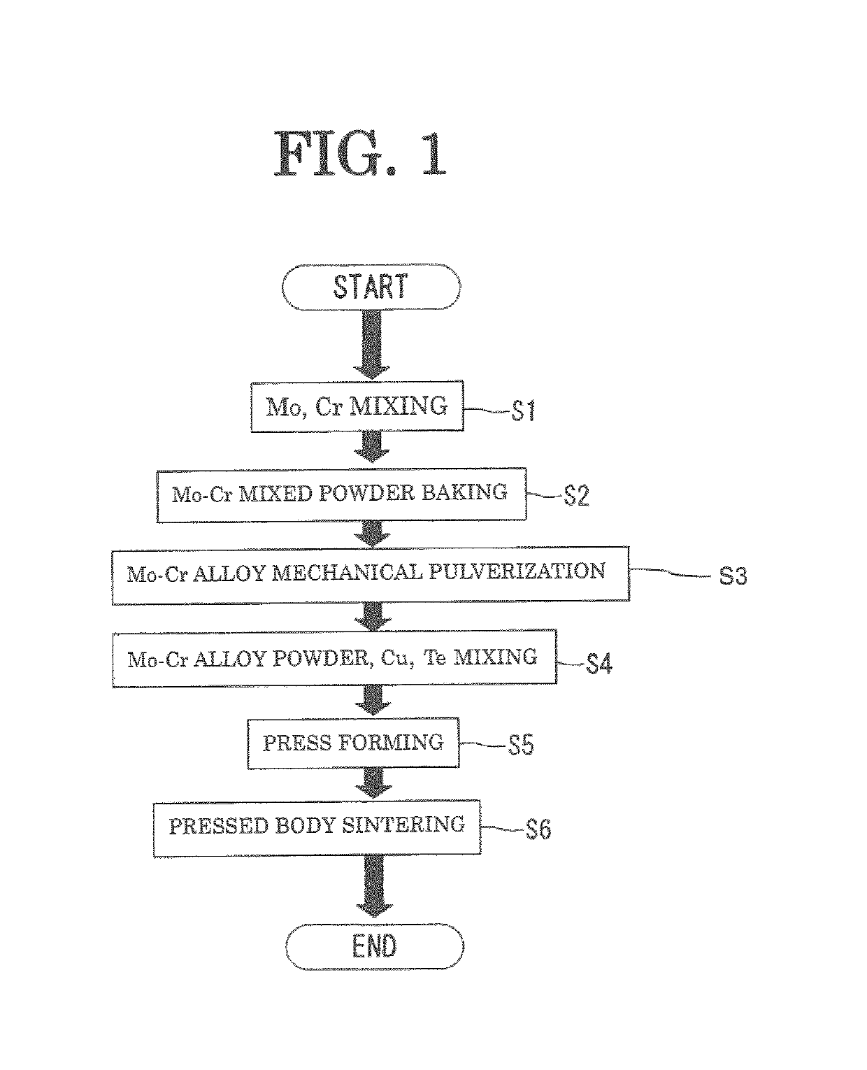
[0062]The electrode material of Example 1 was prepared in accordance with the flow shown in FIG. 1 (the number of samples N=3). In the primary sintering step S6, the compact was sintered at 1030° C. for two hours.

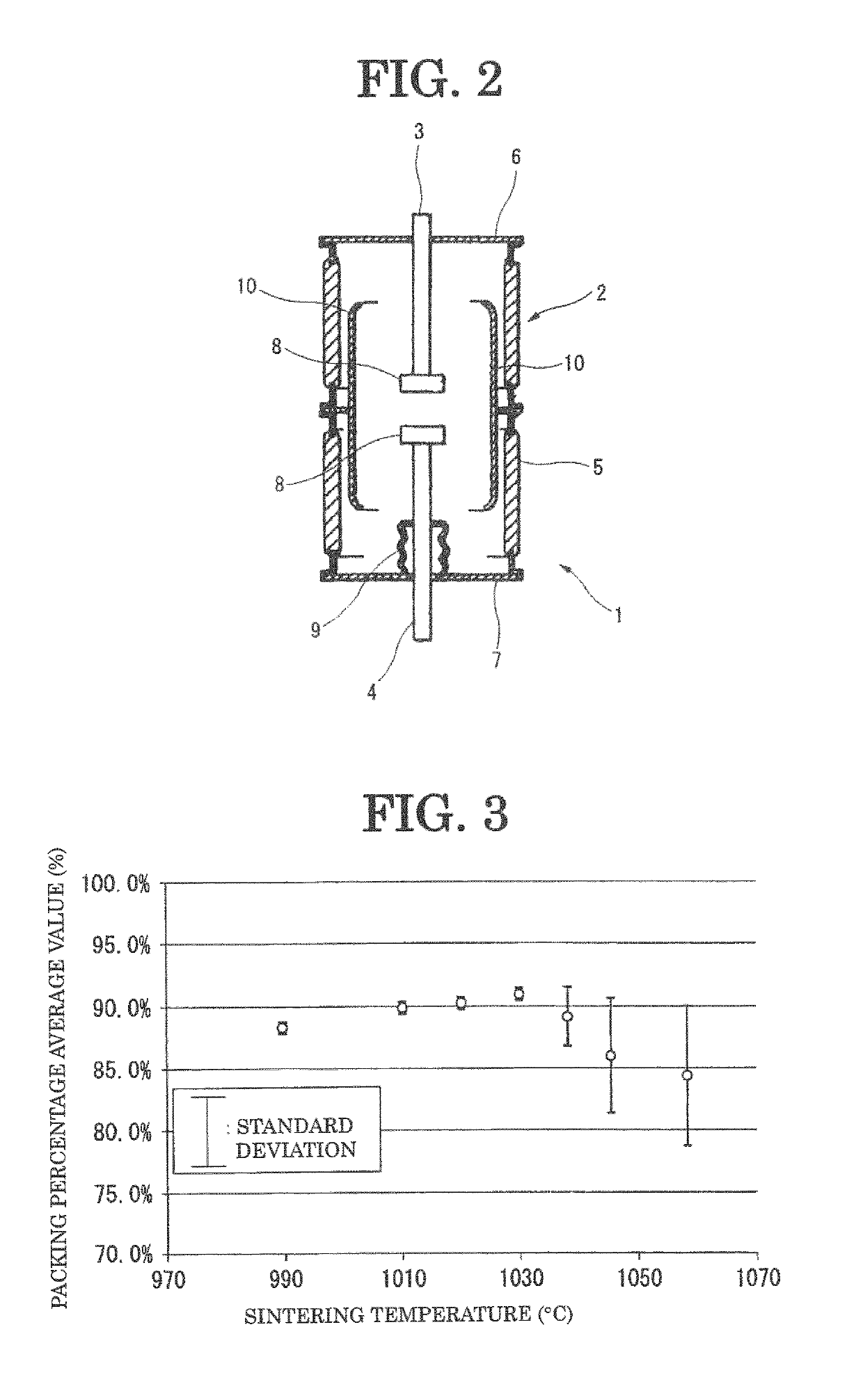
[0063]As shown in Table 1 and FIG. 3, the average value (N=3) of packing percentage of the electrode material of Example 1 was 91%. Furthermore, standard deviation a of packing percentage was 0.4. As a result of checking brazing property of the electrode material of Example 1, brazing property was good. That is, when conducting brazing, fillet was formed, and the electrode material did not come off the lead even when the electrode material was hit with a hammer (Examples 2 and 3 were also similar).

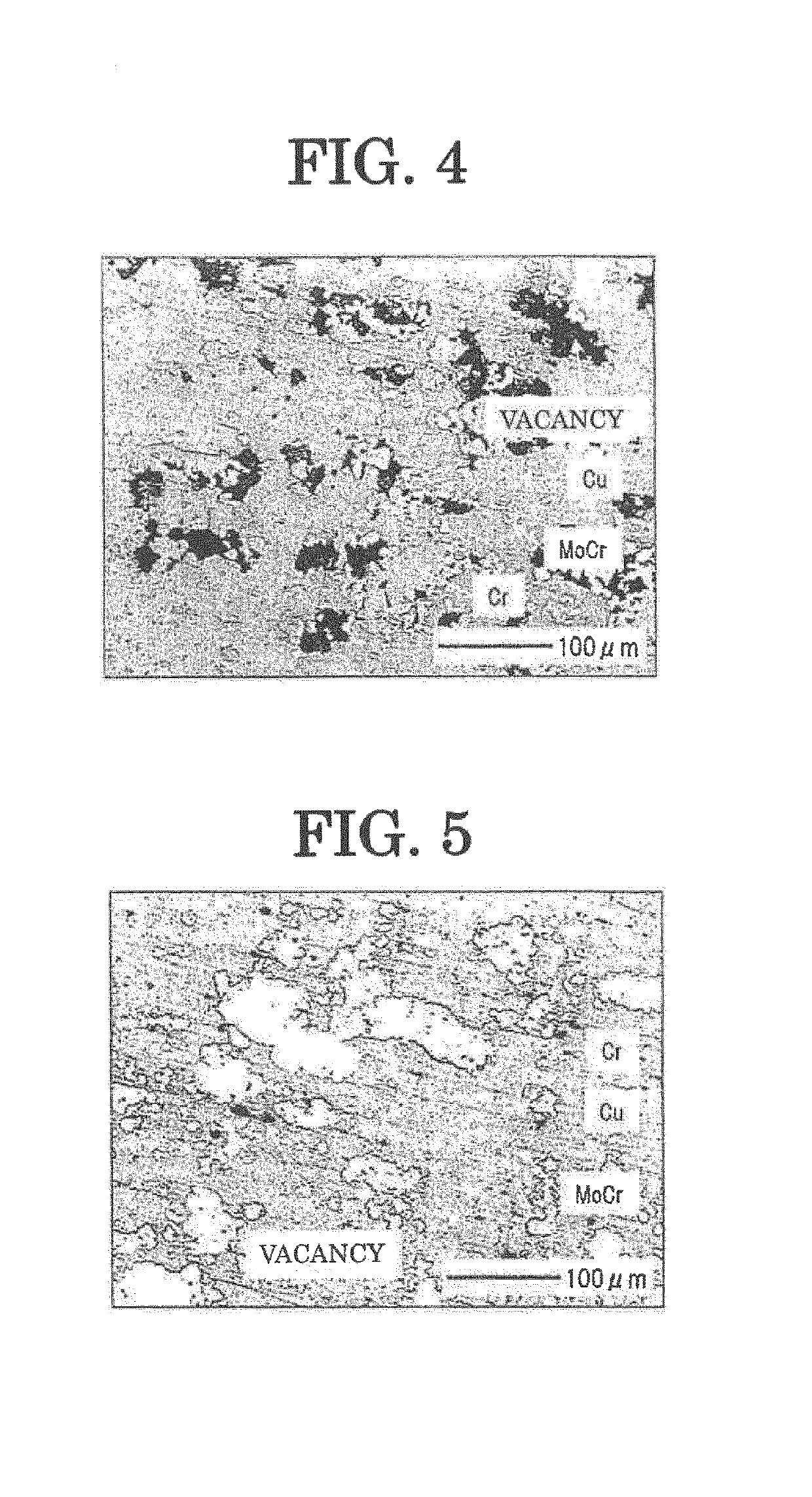
[0064]FIG. 5 shows a sectional microphotograph of the electrode mat...

example 2

[0065]The electrode material of Example 2 is an electrode material prepared by the same method as that of Comparative Example 1, except that the sintering temperature in the primary sintering step S6 was different.

[0066]The electrode material of Example 2 was prepared in accordance with the flow shown in FIG. 1 (the number of samples N=3). In the primary sintering step S6, the compact was sintered at 1020° C. for two hours.

[0067]As shown in Table 1 and FIG. 3, the average value (N=3) of packing percentage of the electrode material of Example 2 was 90%. Furthermore, standard deviation a of packing percentage was 0.5. As a result of checking brazing property of the electrode material of Example 2, brazing property was good.

example 3

[0068]The electrode material of Example 3 is an electrode material prepared by the same method as that of Comparative Example 1, except that the sintering temperature in the primary sintering step S6 was different.

[0069]The electrode material of Example 3 was prepared in accordance with the flow shown in FIG. 1 (the number of samples N=3). In the primary sintering step S6, the compact was sintered at 1010° C. for two hours.

[0070]As shown in Table 1 and FIG. 3, the average value (N=3) of packing percentage of the electrode material of Example 3 was 90%. Furthermore, standard deviation a of packing percentage was 0.4. As a result of checking brazing property of the electrode material of Example 3, brazing property was good.


PUM

PropertyMeasurementUnit
temperatureaaaaaaaaaa
median sizeaaaaaaaaaa

Abstract

It is a method for manufacturing an electrode material containing Cu, Cr, a heat-resistant element, and a low melting metal. A Cr powder and a heat-resistant element powder are mixed together in a ratio such that the Cr is greater than the heat-resistant element by weight. The mixed powder of the heat-resistant element and the Cr powder is baked. A MoCr solid solution obtained by the baking and containing a solid solution of the heat-resistant element and the Cr is pulverized and then classified. The classified MoCr solid solution powder, a Cu powder, and a low-melting metal powder are mixed together, followed by sintering at a temperature that is 1010° C. or higher and is lower than 1038° C., thereby obtaining the electrode material.

Description

TECHNICAL FIELD[0001]The present invention relates to a method for manufacturing an electrode material, which is used for an electrode of vacuum interrupters, etc., and to the electrode material.BACKGROUND ART[0002]The contact material of vacuum interrupters is required to satisfy characteristics, such as (1) the breaking capacity being large, (2) the withstand voltage capability being high, (3) the contact resistance being low, (4) the deposition resistance property being high, (5) the contact consumption being low, (6) the chopped current being low, (7) the workability being excellent, and (8) the mechanical strength being high.[0003]Since some of these characteristics conflict with each other, there is no contact material satisfying all of the above characteristics. Cu—Cr electrode materials have characteristics, such as the breaking capacity being large, the withstand voltage capability being high, and the deposition resistance property being high. Therefore, they are widely use...

Claims


Application Information

Patent Timeline
Patent Type & Authority Patents(United States)
IPC IPC(8): B22F7/00C22C9/00H01H11/04B22F1/00B22F3/00C22C1/04C22C9/10C22C30/02H01H33/664H01H1/02B22F3/10B22F1/05
CPCC22C9/10B22F1/0011H01H1/0206C22C9/00H01H33/664B22F3/10B22F1/00H01H11/048C22C1/04C22C30/02B22F7/00B22F2301/20H01H11/04B22F2301/10C22C1/0425B22F2998/10B22F1/05B22F1/09B22F1/142B22F1/148B22F9/04B22F3/12
Inventor HAYASHI, SHOTAISHIKAWA, KEITAYAMAMURA, KENTAHASEGAWA, KOSUKE
Owner MEIDENSHA ELECTRIC MFG CO LTD
Why Eureka
Try Eureka