Manufacturing method and device for three-dimensional engineered tissue

Active Publication Date: 2019-12-24
ONO JIRO
View PDF21 Cites 0 Cited by
  • Summary
  • Abstract
  • Description
  • Claims
  • Application Information

AI Technical Summary

Benefits of technology

The present invention provides an easier and better method for making three-dimensional cellular structures and supporting devices. This is possible because the invention allows for the removal of thread or needle-shaped parts from cell aggregates after they have fused together. This creates a space where the cells can fill, making the fabrication process simpler than existing methods.

Problems solved by technology

The downside of this method is that scaffold material block oxygen and nutrients delivery to cells.
Furthermore, this patent document claims to “arrange a plurality of cell aggregates according to a pattern such that each of the cell aggregates contacts at least one other cell aggregate,” which requires “arranging according to a pattern.” Also, as shape of these types of three-dimensional cellular structure depends largely on shape retaining capability of scaffold materials, there are limitation in size and shape (especially height direction).
Furthermore, Scaffold will remain inside of three-dimensional Cellular structure, that leaves possibility of potential adverse effect against cell, which causes additional evaluation or approval process when transplanted to human patient.
Furthermore, precise needle location is essential to this process and that requires precise manufacturing, which lead to higher manufacturing cost as well as special equipment to handle needle array.

Method used


Image

  • Manufacturing method and device for three-dimensional engineered tissue
  • Manufacturing method and device for three-dimensional engineered tissue
  • Manufacturing method and device for three-dimensional engineered tissue

Examples


first embodiment

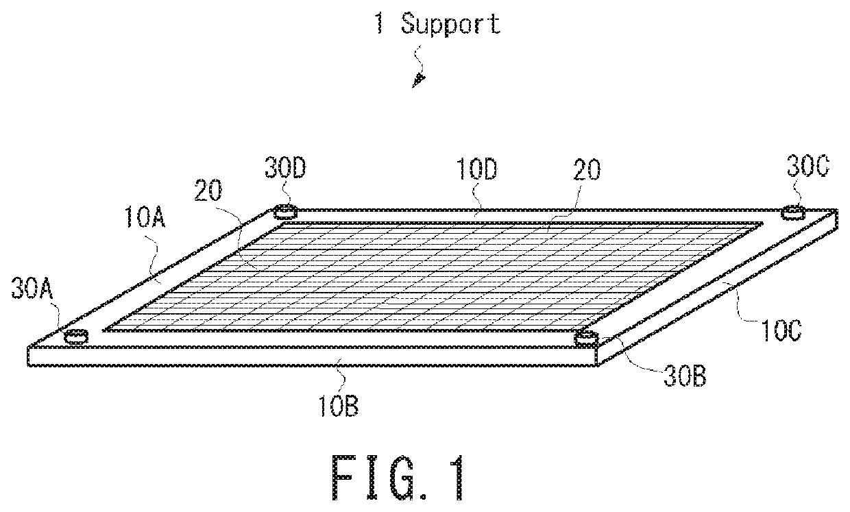
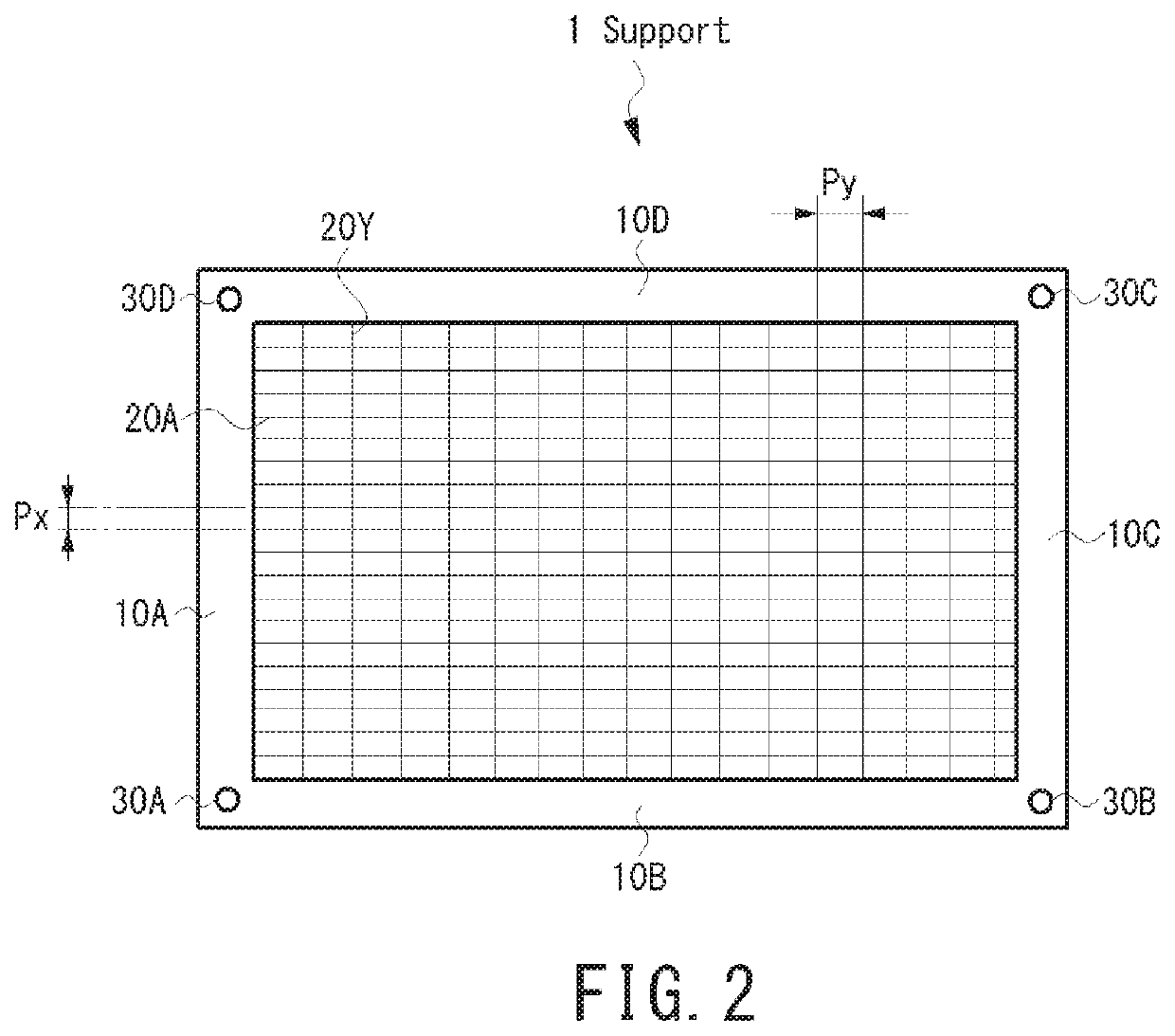
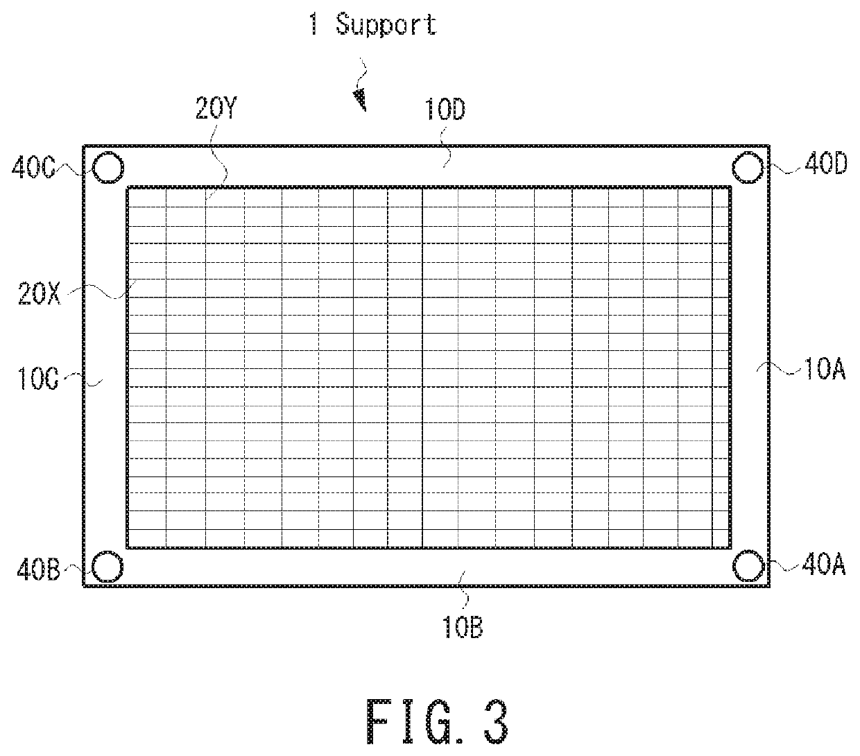
[0054]Below are explanations of embodiments. FIG. 1 is perspective view of first embodiment of support for three-dimensional cellular structure fabrication. FIG. 2 is plain view of the support shown in FIG. 1. FIG. 3 is Rear view of the support shown in FIG. 1. Support 1 comprises a frame 10A, frame 10B, frame 10C, and frame 10D forming four side of frame (called hereinafter frame 10 as a whole frame), multiple string member forming net or matrix shaped space inside of frame 10, alignment measure to align each frame when layered.

[0055]Frame 10 can be made of arbitrary materials, such as resin. Also, size of frame 10 can be any size, as an example one side length can be 3-4 cm and thickness can be 0.1-1.0 mm when cell aggregate size is around 200 um.

[0056]String Member 20 exists in direction of X and Y inside of frame 10. String member 20 can be made with materials such as stainless steel, nylon, polyester, and diameter can be 10 um as one example. Preferably string member 20 is coat...

second embodiment

[0072]FIG. 12A shows schematic diagram of support used for In this embodiment, support 1 has string member 20x in x direction is located in width Lx, and string member 20y in y direction is located in width Ly. From this, support 1 has net shaped space only in between width Lx and Ly. Area 25, which does not have string member, will not hold cell aggregate which is dispensed from dispenser 200. Consequently, three-dimensional cellular structure is formed on Width Lx, Ly area.

[0073]The above mentioned example used rectangular space Lx, Ly, but space shape can be different. For example, as shown in FIG. 12B, multiple rectangular space S1, S2, S3 and S4 can be formed inside of support. In this case, four three-dimensional cellular structures which have corresponding shape to S1, S2, S3 and S4 are obtained at one process.

[0074]In second embodiment as well as used in first embodiment, multiple support shall be layered according to the height of designed three-dimensional cellular struct...

seventh embodiment

[0097]Next, the seventh embodiment is described. FIGS. 22A-22C show how 3D support is made by 3D Printer. In this embodiment, this 3D support is called as mold 700. Mold 700 is made with non-toxic material to human being. Preferably, mold 700 is made with material such as polycarbonate which has high melting temperature for high temperature sterilization. Also preferably, mold 700 is coated with non-adherent material to prevent cell adhesion to mold.

[0098]Mold 700 comprise, as shown in FIG. 22A, upper part 710 and lower part 720. Upper part 710 and lower part 720 possess net shaped area where cell aggregates are held and they are made by 3D printer. When cell aggregate is filled in mold and cell aggregate is fused, in order to remove three-dimensional cellular structure from mold 700, mold 700 is separated to upper part 710 and lower part 720 at cutting position Dv.

[0099]Upper part 710 comprises top and side members. Multiple filling holes 702 are connected to the inner space on the...


PUM


Abstract

A method for fabricating a cellular structure is disclosed. The method includes feeding cell aggregates onto a plurality of thread or needle shaped members in each of a plurality of supports. Each member forms net or mesh shaped spaces in the respective support. The method also includes layering the supports with the cell aggregates fed therein, culturing the cell aggregates to fuse, and removing the plurality of thread or needle shaped members from the fused cellular structure.

Description

CROSS-REFERENCE TO RELATED APPLICATIONS[0001]This application is a continuation of co-pending International Application No. PCT / JP2016 / 076987, which was filed on Sep. 13, 2016 and is incorporated herein by reference.TECHNICAL FIELD[0002]This invention relates generally to the field of fabricating of three-dimensional engineered tissue using cell aggregates, especially the method of fabricating three-dimensional engineered tissue using the net-like shape or mesh-like supports.BACKGROUND[0003]As world population increases as well as prolonged human lifetime span, needs, desires and demands for medical treatments are only elevating. In recent years, a new approach, Tissue Engineering, which utilizes living cell, is spotlighted. The ultimate goal of Tissue Engineering is to fabricate artificial tissue and organ for transplantation to human body. Artificial tissue is fabricated part of the body which expresses particular functionality when transplanted to human body. However, transplanta...

Claims


Application Information

Patent Timeline
IPC IPC(8): C12N5/00A61L27/38C12M1/00C12M3/06
CPCC12N5/0068C12M27/16A61L27/3895C12N5/0062C12M1/00C12N2513/00C12N2535/00
Inventor ONO, JIRO
Owner ONO JIRO
Why Eureka
Try Eureka