
Multi-focus optics

a multi-focus, optics technology, applied in the field of optics, can solve the problems of material disruption due to multi-photon absorption or thermal stress, increase processing time, and high toleran

Active Publication Date: 2019-12-31
ADLOPTICA OPTICAL SYST
View PDF35 Cites 4 Cited by
  • Summary
  • Abstract
  • Description
  • Claims
  • Application Information

AI Technical Summary

Benefits of technology

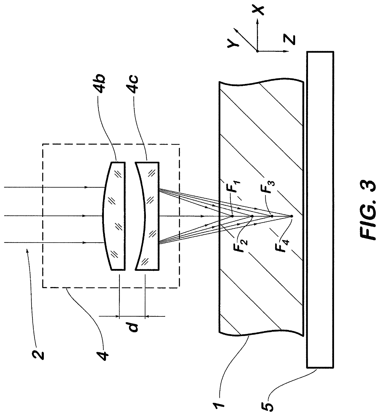
The present invention provides methods, systems, devices and apparatus for laser processing materials by focusing laser radiation using an optical system forming at least three separate focuses. This allows for elongated processed volume regions and reduces the number of processing passes, increasing processing speed. Additionally, a scanning device can realizes motion of the focusing optical system over unmoved workpiece being held using a holding device, providing repeating of the processing effect along a processing path.

Problems solved by technology

However, material disruption can occur due to multiphoton absorption or thermal stress is used in laser technologies of cutting, chamfering, singulation, dicing, drilling of brittle materials, for example various types of glasses, sapphire, silicon, other transparent and semi-transparent materials, as well as multilayer structures.
However, there are disadvantages of this method, such as increasing of processing time, high tolerances for alignment between processing paths on each step, and high roughness of the cutting edge reducing the bending strength.
Common disadvantages of those methods include complexity and high costs of realization, tough tolerances to specifications of laser radiation, and difficulty to control the depth of the processed region.
The disadvantages of DOE-based optical systems can include high initial manufacturing costs, limited efficiency and low resistance to powerful laser radiation, especially to widely-used ultra-short pulse lasers, and sensitivity to input beam size and quality.
The tough tolerances to laser specifications and limited number of materials that can be processed are disadvantages of these methods.
The manufacturing of such optics can be complex and expensive.
Another disadvantage is the presence of junction between parts of the optical surface, which reduces resistance to powerful laser radiation, especially to widely-used ultra-short pulse lasers.
However, the IOL cannot be applied in laser material processing because these optics are cemented and made from polymers.
A disadvantage is using cemented optics, which reduces resistance to powerful laser radiation, especially to widely-used ultra-short pulse lasers.
Thus, it is impossible to change the length of elongated processed region by increasing the focuses number and changing distance between focuses.
This sets a limitation on thickness of materials to be processed and requires the repetition of processing path in case of thick materials, which reduces the process productivity.
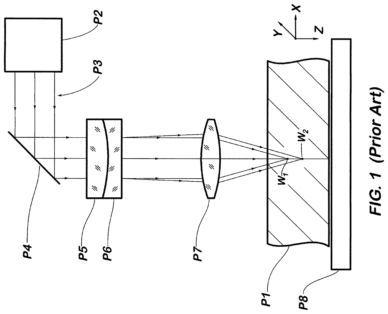
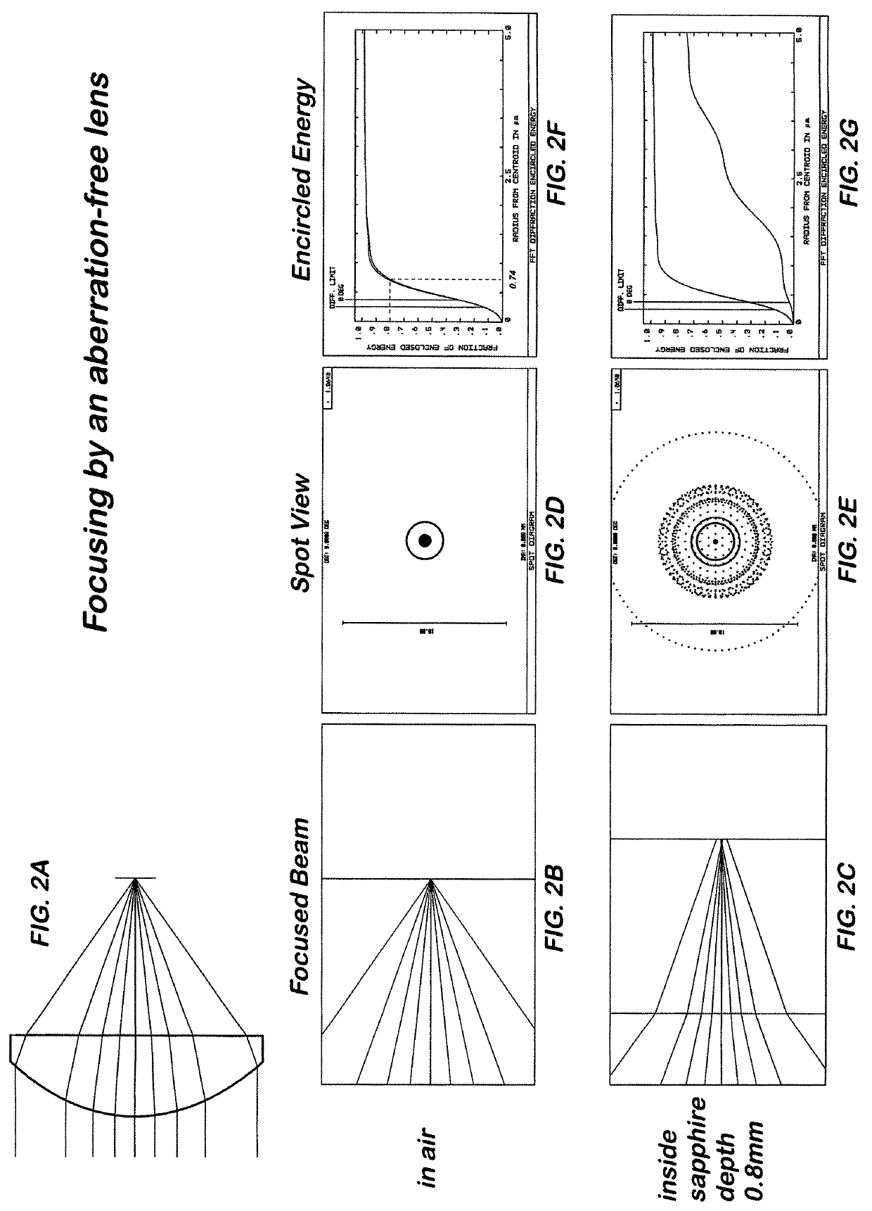
A disadvantage of conventional technical solutions is the absence of ways to compensate aberrations induced by a transparent material workpiece while light focusing inside the said workpiece.
From the point of view of modern requirements to material processing using laser beam focusing the conventional techniques are not optimal.

Method used


Image

  • Multi-focus optics
  • Multi-focus optics
  • Multi-focus optics

Examples


Embodiment Construction

[0056]Before explaining the disclosed embodiments of the present invention in detail it is to be understood that the invention is not limited in its applications to the details of the particular arrangements shown since the invention is capable of other embodiments. Also, the terminology used herein is for the purpose of description and not of limitation.

[0057]In the Summary above and in the Detailed Description of Preferred Embodiments and in the accompanying drawings, reference is made to particular features (including method steps) of the invention. It is to be understood that the disclosure of the invention in this specification includes all possible combinations of such particular features. For example, where a particular feature is disclosed in the context of a particular aspect or embodiment of the invention, that feature can also be used, to the extent possible, in combination with and / or in the context of other particular aspects and embodiments of the invention, and in the...


PUM

PropertyMeasurementUnit
depthaaaaaaaaaa
depthaaaaaaaaaa
diameteraaaaaaaaaa

Abstract

Methods, systems, devices and apparatus for laser processing of transparent or partially transparent materials by focusing laser radiation on a surface of a material workpiece or inside the material workpiece and creating elongated processed regions with variable and controlled depth using focusing optical system with air-spaced optical components, forming three or more multiple focuses along the optical axis and compensating aberrations induced while light focusing inside the material workpiece. The focusing optical system can have an aplanatic design, with lenses made from birefringent materials combined with lenses from isotropic materials, or objectives, or zoom optical system, or waveplates. Material processing effects such as material disruption or modification of material properties are produced due to the interaction of focused laser radiation with material in elongated volume processed regions and are multiple repeated along the processing path by relative motion between the material workpiece and the focusing optical system being realized with a scanning device.

Description

FIELD OF INVENTION[0001]The present invention relates to the field of optics, and more particular to methods, apparatuses, devices and systems for laser material processing for cutting, welding, scribing and drilling of non-metallic and metallic materials, and in particular, brittle materials, with multi-focus optics.BACKGROUND TO THE INVENTION[0002]Lasers are widely-used in various industrial material processing techniques due to the capability to provide high energy concentration in a spot by focusing of a laser beam. The physical effects happening while interaction of material and concentrated laser energy can lead to necessary processing effects; such as for example, melting and evaporation of metals and non-metallic materials like glass, Carbon Fiber Reinforced Polymers (CFRP) are important in laser welding and cutting applications. However, material disruption can occur due to multiphoton absorption or thermal stress is used in laser technologies of cutting, chamfering, singul...

Claims


Application Information

Patent Timeline
Patent Type & Authority Patents(United States)
IPC IPC(8): B23K26/21B23K26/06B23K26/00B23K26/08B23K26/082B23K103/00B23K103/02B23K103/08
CPCB23K26/0869B23K26/082B23K26/083B23K26/21B23K26/0643B23K26/0006B23K26/0648B23K2103/08B23K2103/54B23K2103/42B23K2103/02B23K2103/52B23K26/0617B23K26/53B23K2103/56
Inventor LASKIN, ALEXANDERLASKIN, VADIM
Owner ADLOPTICA OPTICAL SYST
Learn More