
Battery and assembly method therefor

a battery and assembly method technology, applied in the field of batteries, can solve the problems of short circuit between the negative electrode and the positive electrode, battery has not yet been put into practice, etc., and achieve the effects of preventing the short circuit caused by dendritic zinc, high voltage, and efficient assembly

Active Publication Date: 2019-12-31
NGK INSULATORS LTD
View PDF13 Cites 0 Cited by
  • Summary
  • Abstract
  • Description
  • Claims
  • Application Information

AI Technical Summary

Benefits of technology

[0007]The applicant has already successfully developed a highly-densified ceramic separator (inorganic solid electrolyte separator) exhibiting hydroxide ion conductivity and yet water impermeability. The present applicant has also successfully formed such a ceramic separator on a porous substrate (e.g., an alumina porous substrate). The use of such a separator (or a separator provided with a porous substrate) in a secondary battery, such as a zinc-nickel battery, can prevent the short circuit caused by dendritic zinc. The maximization of such an effect requires reliable separation of the positive electrode side from the negative electrode side by a hydroxide-ion-conductive ceramic separator in a battery container. In particular, it is advantageous if a stacked-cell battery having such a configuration could be efficiently assembled from a plurality of unit cells to achieve high voltage and high current.
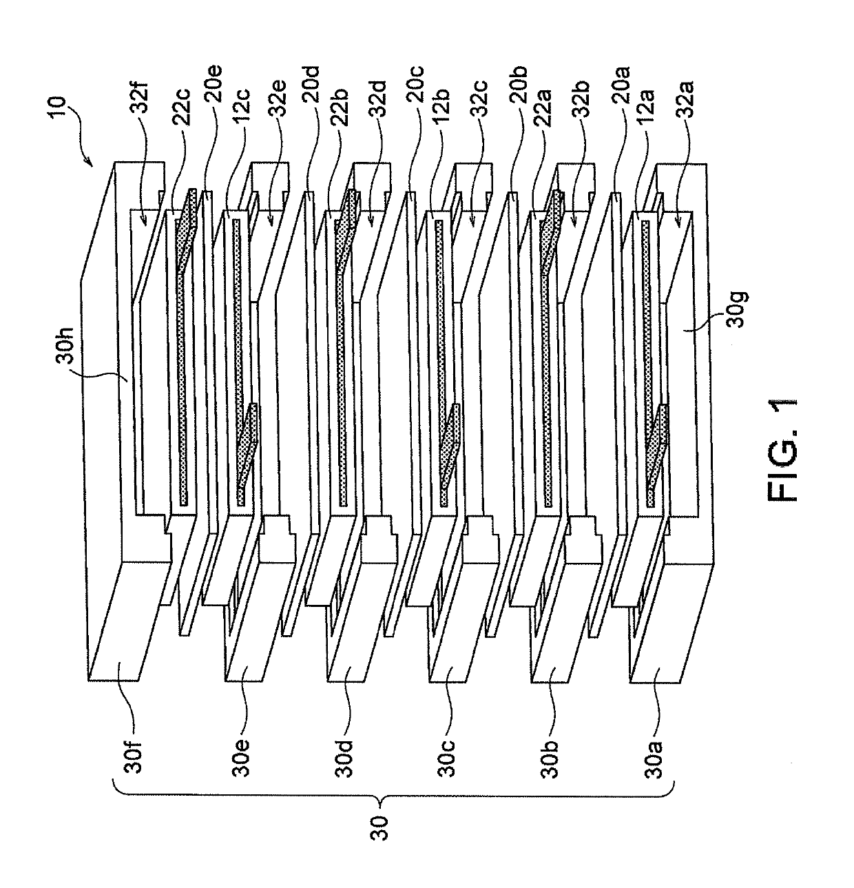
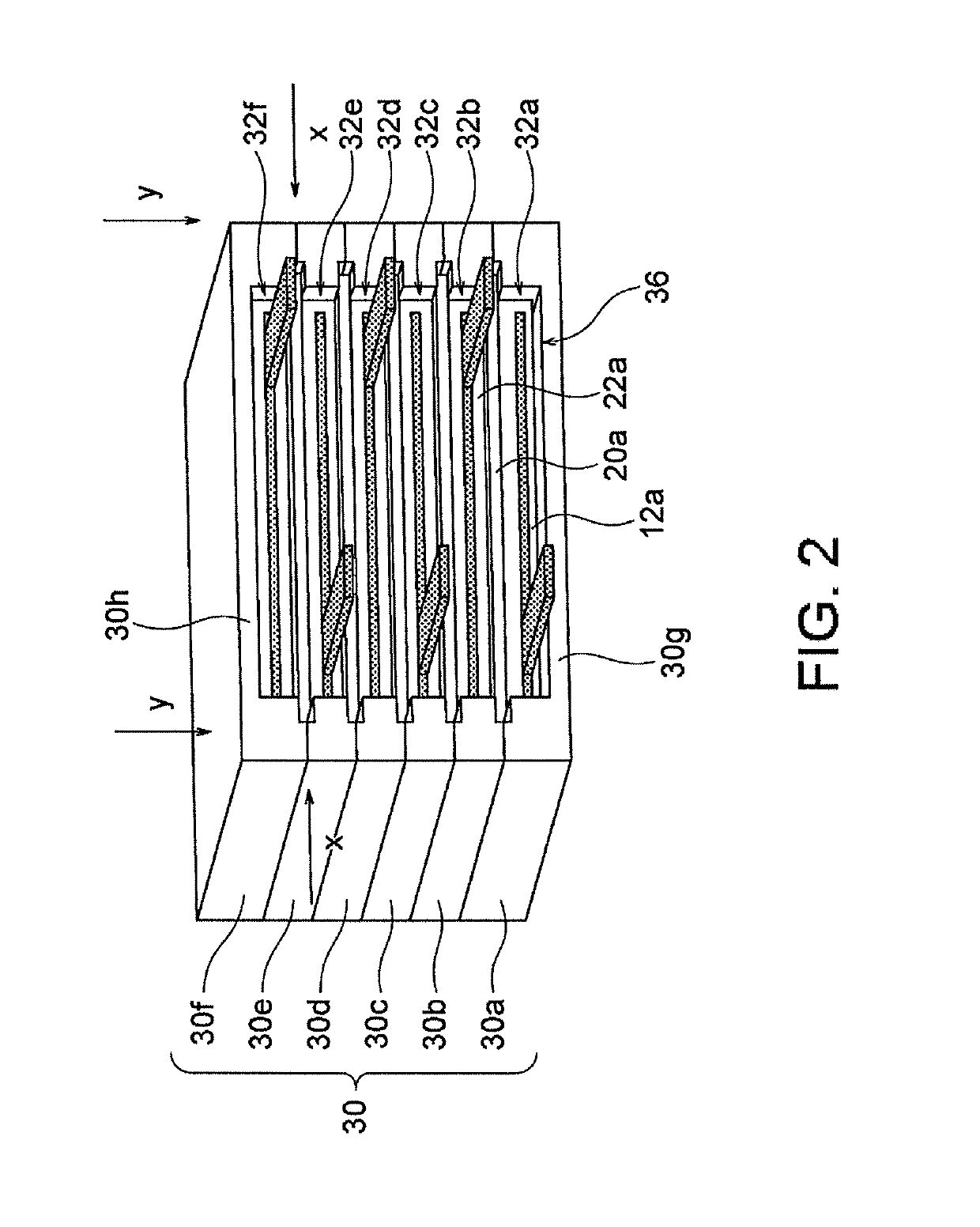
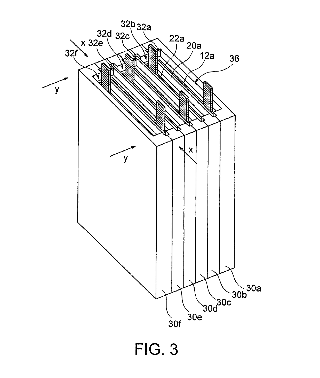
[0008]The inventors have recently found that a battery with a desired number of layers can be assembled sequentially and efficiently from one or more positive electrode plates, one or more negative electrode plates, and one or more separator structures exhibiting hydroxide ion conductivity and water impermeability, while the positive and negative electrode sides are reliably separated by the separator structures.

Problems solved by technology

Unfortunately, these batteries have not yet been put into practice.
This is due to a problem that zinc contained in the negative electrode forms dendritic crystals, i.e. dendrites, during a charge mode of the battery and the dendrites break the separator to cause short circuit between the negative electrode and the positive electrode.

Method used


Image

  • Battery and assembly method therefor
  • Battery and assembly method therefor
  • Battery and assembly method therefor

Examples


example 1

on and Evaluation of LDH Separator with Porous Substrate

(1) Preparation of Porous Substrate

[0118]Boehmite (DISPAL 18N4-80, manufactured by Sasol Limited), methyl cellulose, and ion-exchange water were weighed in proportions by mass of 10:1:5, and were then kneaded together. The kneaded product was subjected to extrusion molding with a hand press into a plate having a size sufficiently exceeding 5 cm×8 cm and a thickness of 0.5 cm. The resultant green body was dried at 80° C. for 12 hours and then fired at 1,150° C. for three hours, to prepare an alumina porous substrate. The porous substrate was cut into a piece of 5 cm×8 cm.

[0119]The porosity at the surface of the resultant porous substrate was determined by a method involving image processing. The porosity was 24.6%. The porosity was determined as follows: 1) a scanning electron microscopic (SEM) image of the surface microstructure of the porous substrate was taken with a scanning electron microscope (SEM; JSM-6610LV, manufactured...

example 2 (

Reference): Production and Evaluation of Nickel-Zinc Battery

[0131]Example 2 is a reference example based on a unit cell including a single set of a positive electrode plate, a separator, and a negative electrode plate.

(1) Preparation of Separator with Porous Substrate

[0132]A separator provided with a porous substrate (LDH membrane on alumina substrate) (size: 5 cm×8 cm) was prepared as in Example 1.

(2) Preparation of Positive Electrode Plate

[0133]Particulate nickel hydroxide containing zinc and cobalt in the form of solid solution was prepared. The particulate nickel hydroxide was coated with cobalt hydroxide to yield a positive-electrode active material. The positive-electrode active material was mixed with a 2% aqueous carboxymethyl cellulose solution to prepare a paste. The paste was evenly applied to a current collector composed of a nickel porous substrate having a porosity of about 95% and dried so that the porosity of the positive-electrode active material was 50% to prepare ...

example 3

onding of ABS Resin

[0138]Five ABS resin plates with a thickness of 1 mm were joined by solvent bonding into a box container. More specifically, two resin plates 302 were fixed together with a zig 304 such that the edges of the resin plates 302 were in contact with each other at an angle of 90 degrees, methyl ethyl ketone (MEK) solvent was applied to the joint portion 306 between the resin plates 302 with a brush 308, and then a solvent was poured into the gap in the joint portion, as shown in FIG. 20. In the present Example, the two resin plates 302 were tightly fixed together so as to reduce the gap in the joint portion 306, and then the solvent was poured therein. As a result, the solvent spread in and around the gap due to capillary action. Such a procedure was repeated until the five resin plates 302 were mutually solvent-bonded. The box container 300 shown in FIG. 20 was thereby produced. Finally, it was confirmed whether a gap due to inadequate bonding was present at the joint...


PUM

PropertyMeasurementUnit
temperatureaaaaaaaaaa
thicknessaaaaaaaaaa

Abstract

The present invention provides a sequential and efficient method of assembling a battery with a desired number of layers while reliably separating positive and negative electrode sides from each other with one or more separator structures. According to the invention, the method of assembling a battery includes stacking one or multiple combinations each comprising a frame and a positive electrode plate to be disposed in a region defined by the frame and one or multiple combinations each comprising a frame and a negative electrode plate to be disposed in a region defined by the frame, once or alternately, such that the positive and adjacent negative electrode plates are separated from each other by a separator structure and the periphery of the separator structure is held between the adjacent frames. The separator structure includes a separator exhibiting hydroxide ion conductivity and water impermeability.

Description

CROSS-REFERENCE TO RELATED APPLICATIONS[0001]This application is a continuation application of PCT / JP2015 / 084300 filed Dec. 7, 2015, which claims priority to Japanese Patent Application No. 2015-056315 filed Mar. 19, 2015 and Japanese Patent Application No. 2015-165111 filed Aug. 24, 2015, the entire contents all of which are incorporated herein by reference.BACKGROUND OF THE INVENTION1. Field of the Invention[0002]The present invention relates to a battery and a method of assembling the same.2. Description of the Related Art[0003]Zinc secondary batteries, such as nickel-zinc secondary batteries, have been developed and studied over many years. Unfortunately, these batteries have not yet been put into practice. This is due to a problem that zinc contained in the negative electrode forms dendritic crystals, i.e. dendrites, during a charge mode of the battery and the dendrites break the separator to cause short circuit between the negative electrode and the positive electrode. Thus, a...

Claims


Application Information

Patent Timeline
Patent Type & Authority Patents(United States)
IPC IPC(8): H01M10/04H01M2/20H01M2/08H01M10/34H01M10/30H01M4/32H01M4/42H01M4/02H01M50/434
CPCH01M10/345H01M2/08H01M10/0486H01M2/202H01M10/30H01M4/42H01M4/32H01M2004/028H01M2004/027H01M10/0413H01M10/0561H01M10/281H01M12/08H01M2300/0014Y02E60/10H01M50/103H01M50/15Y02P70/50H01M50/434
Inventor KITOH, KENSHINYAMADA, NAOHITOKAWAMURA, KENJIGONDA, YUICHI
Owner NGK INSULATORS LTD
Learn More