Method and device for the detection of corrosion within an at least partially electrically conductive housing of an electric energy storage unit and corresponding electric energy storage system

a technology of electrical energy storage unit and at least partially electrically conductive housing, which is applied in the direction of safety/protection circuits, instruments, batteries, etc., can solve the problems of corrosion from the inside leakage of the battery cell, and easy electrochemical reaction of the metal housing, so as to speed up the detection of corrosion and avoid unnecessary checks of the electric energy storage unit

Active Publication Date: 2019-12-31
ROBERT BOSCH GMBH +1
View PDF7 Cites 0 Cited by
  • Summary
  • Abstract
  • Description
  • Claims
  • Application Information

AI Technical Summary

Benefits of technology

[0005]The method for the detection of corrosion in an at least partially electrically conductive housing of an electric energy storage unit comprises several steps and the electric energy storage unit has a positive terminal and features a resistance element with a preassigned electrical resistance value between the positive terminal and the at least partially electrically conductive housing. The method comprises determining state of charge values of the electric energy storage unit for at least one first instant of time and at least one second instant of time and / or determining an electrical isolation resistance value between the housing of the electric energy storage unit and at least one reference point which is situated outside of the electric energy storage unit for at least one third instant of time. The method further comprises a first comparison of a difference of the determined state of charge values with a predefined state of charge difference value for the electric energy storage unit and / or a second comparison of the determined electric isolation resistance value with a predefined electric isolation resistance value for the electric energy storage unit. Depending on the first comparison result and / or the second comparison result a signal is generated concerning the detection of corrosion. The predefined values act as thresholds to assess the occurence of corrosion. This is advantageous because determining the state of charge values and determining the electrical isolation resistance value are already available functionalities which are used here in combination with carefully predefined values so that additional information can be extracted apart from the mere numerical values. The determination and comparison of the state of charge values is particularly well suited when a state of charge determination uncertainty, i.e. the uncertainty to which the real state of charge can be determined and distinguished from other state of charge values, is low, i.e. the state of charge value can be determined with high accuracy and reliably distinguished from other state of charge values because an inherent imprecision or uncertainty of the determined state of charge value is low. In conjunction with a low self-discharge current of the electric energy storage unit, this creates favorable conditions for this variant. Another variant, relying on the determination of the electrical isolation resistance value, will always detect corrosion but also other electrical isolation fault cases. Combining the advantages of both variants is another variant improving reliability and discrimination power of different fault cases.
[0016]Additionally, in case of the determination of the electrical isolation resistance value, a future evolution of the electrical isolation resistance value may be forecast using the determined at least one third electrical isolation resistance value. Using the forecast, a fourth instant of time for a further determination of the electrical isolation resistance value between the housing and the at least one reference may be scheduled. Thus, when a predefined critical level of the electrical isolation resistance value will be reached, the determination can be performed more often to more closely survey the electrical isolation resistance value. Before this point in time, a sporadic determination may be sufficient. Furthermore, this even allows to prearrange a repair shop appointment as a time period can be determined where safe operation of the electric energy store unit is not at risk or possibly dangerous. Thus, unnecessary checks of the electric energy storage unit can be avoided and additional service can be provided to the owner of the electric energy storage unit.

Problems solved by technology

However, under certain conditions, the metallic housing is prone to electrochemical reactions which may occur inside the cell, for example in areas of the housing which are in contact with an electrolyte.
Electric potential gradients within a battery cell may enable these reactions which can lead to corrosion from the inside of the battery cell.
Finally, this may even cause leakage of the battery cell.
The electrically conductive measuring wire is hence also exposed to a possibly corrosive environment.

Method used


Image

  • Method and device for the detection of corrosion within an at least partially electrically conductive housing of an electric energy storage unit and corresponding electric energy storage system
  • Method and device for the detection of corrosion within an at least partially electrically conductive housing of an electric energy storage unit and corresponding electric energy storage system
  • Method and device for the detection of corrosion within an at least partially electrically conductive housing of an electric energy storage unit and corresponding electric energy storage system

Examples


first embodiment

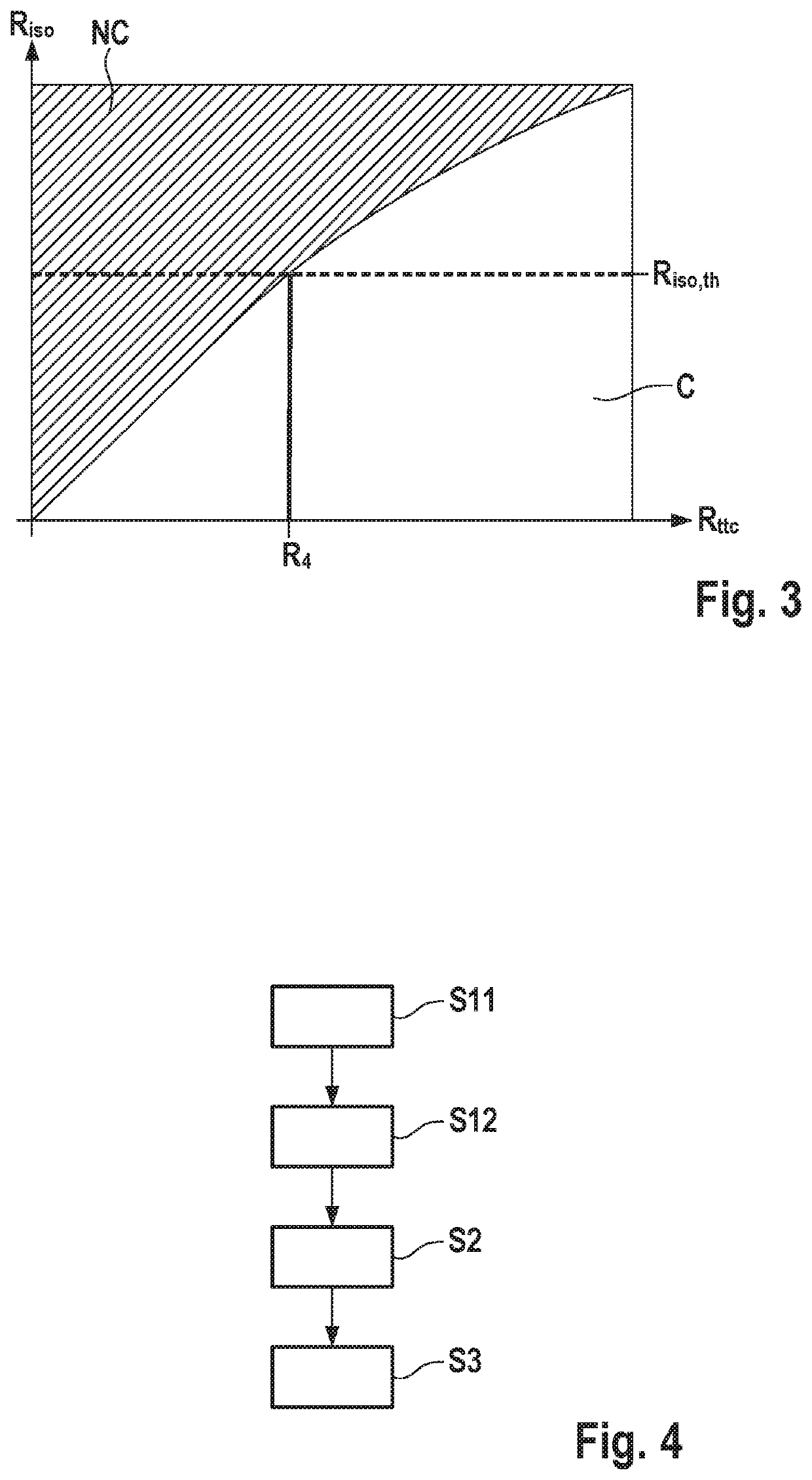
[0024]FIG. 4 shows a flow diagram of the method according to the invention.

second embodiment

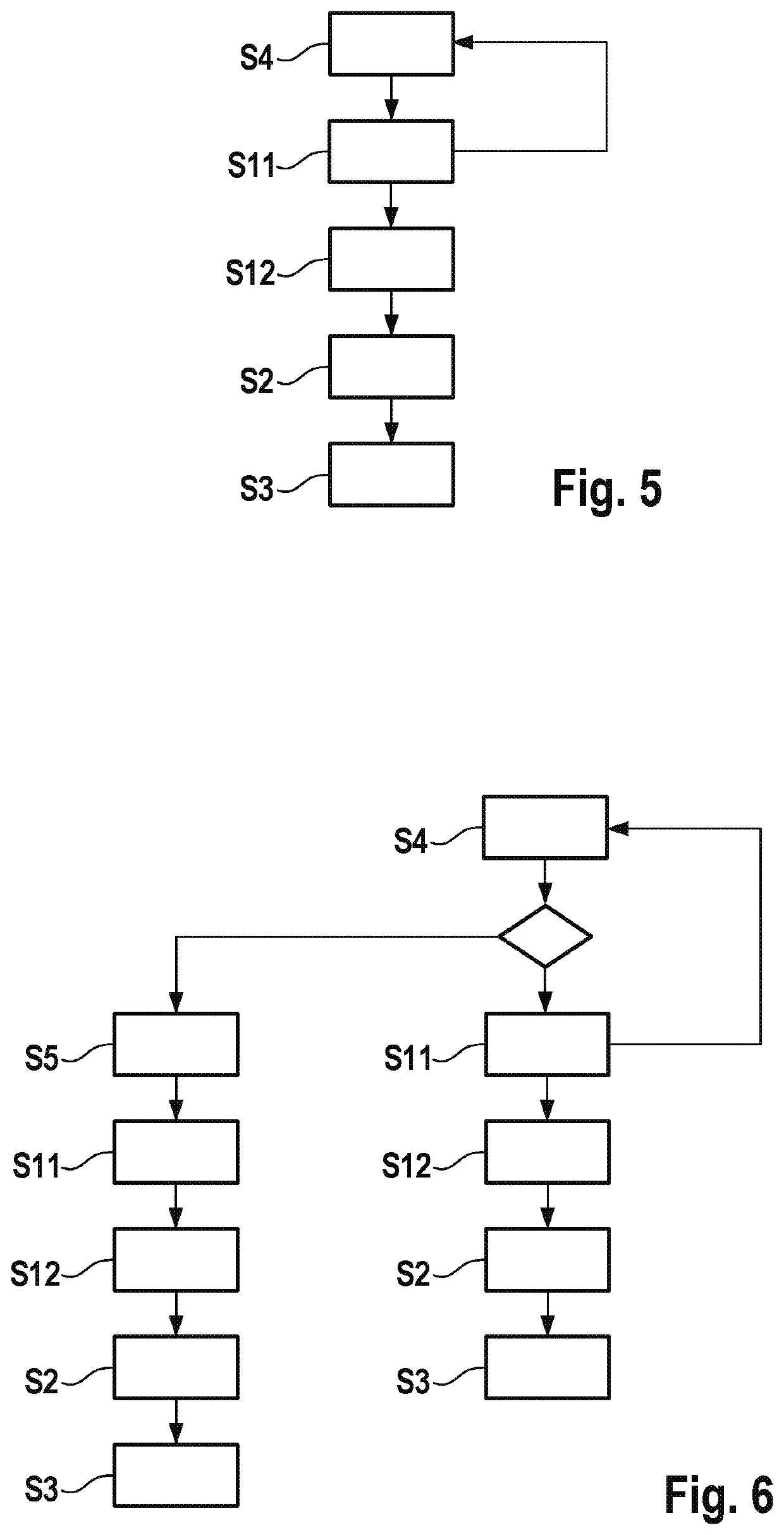
[0025]FIG. 5 shows a flow diagram of the method according to the invention.

third embodiment

[0026]FIG. 6 shows a flow diagram of the method according to the invention.

DETAILED DESCRIPTION

[0027]Identical reference signs refer to identical features in all figures.

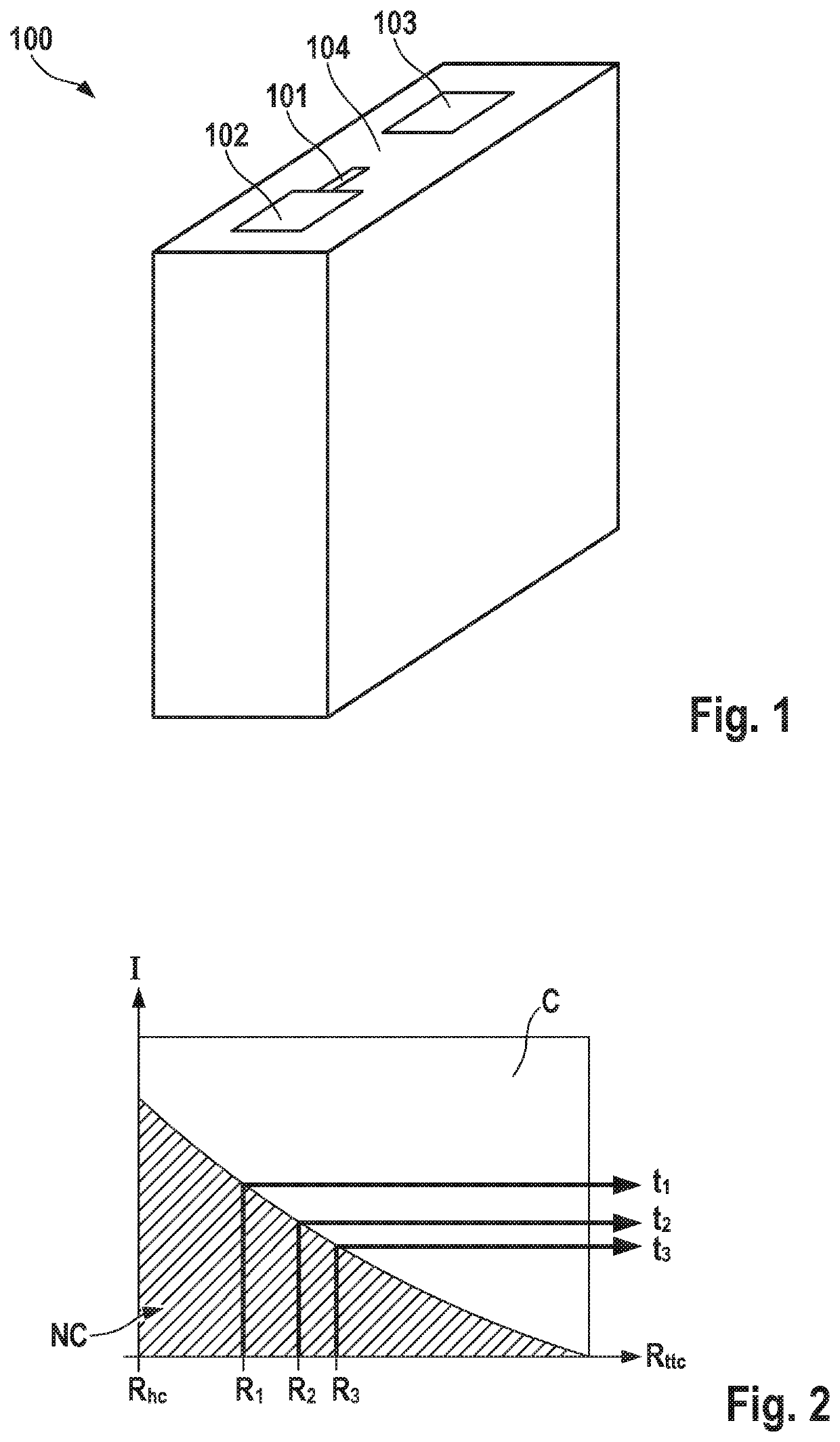
[0028]FIG. 1 shows an electric energy storage unit 100, which has a positive terminal 102 and a negative terminal 103. The electric energy storage unit 100, which in this embodiment is a battery cell, 100 further comprises a metallic housing 104. A resistance element 101 with a preassigned electrical resistance value is installed between the positive terminal 102 and the metallic housing 104 which electrically connects the metallic housing 104 and the positive terminal 102. In this embodiment, an explicit electrical component, for example a resistor with a preassigned electrical resistance value, is used. However, the resistance element 101 may also be embodied by a well-designed interface between the housing 104 and electrochemically active parts, like the jellyroll, of the battery cell. Well-designed in this conte...


PUM

PropertyMeasurementUnit
timeaaaaaaaaaa
instant of timeaaaaaaaaaa
currentsaaaaaaaaaa

Abstract

Detection of corrosion within an at least partially electrically conductive housing of an electric energy storage unit. The electric energy storage unit has a positive terminal and a resistance element between the positive terminal and the housing. State of charge values of the electric energy storage unit for at least one first instant of time and at least one second instant of time are determined. An electrical isolation resistance value between the housing of the electric energy storage unit and at least one reference point for at least one third instant of time may also be determined. A first comparison of a difference of the determined state of charge values with a predefined state of charge difference value for the electric energy storage unit and / or a second comparison of the determined electrical isolation resistance value with a predefined electrical isolation resistance value for the electric energy storage unit are performed.

Description

BACKGROUND OF THE INVENTION[0001]The present invention emanates from a method and a device for the detection of corrosion in an at least partially electrically conductive housing of an electric energy storage unit as well as an electric energy storage system.[0002]In many applications, e.g. in the automobile field, battery cells, which are based on lithium-ion technology, have a metallic housing. This provides mechanical stability and prevents liquids from entering into electrically sensitive areas. This is especially important in the automotive field where safety requirements are high and must not be compromised as lives could be at stake. However, under certain conditions, the metallic housing is prone to electrochemical reactions which may occur inside the cell, for example in areas of the housing which are in contact with an electrolyte. Electric potential gradients within a battery cell may enable these reactions which can lead to corrosion from the inside of the battery cell. ...

Claims


Application Information

Patent Timeline
Patent Type & Authority Patents(United States)
IPC IPC(8): H01M10/42G01R31/392G01N17/02H01M2/34H01M10/48H02J7/00
CPCH01M10/482H01M10/4228H01M2/34G01N17/02G01R31/392H02J7/0029H01M2200/00G01R31/382G01N17/00H01M10/48H01M2010/4271Y02E60/10
Inventor HUBER, BERNHARDSTIMM, FRANKKOHN, PETERLANGE, ULRICH
Owner ROBERT BOSCH GMBH
Why Eureka
Try Eureka