
Downhole fluid properties optical analysis probe having a removable optical tip

a technology of fluid properties and optical analysis probes, which is applied in the direction of fluorescence/phosphorescence, borehole/well accessories, etc., can solve the problems of difficult disassembly of complex assemblies, damage to the optical tip of the optical analysis probe, and high shock environment of wireline or drilling or production logging operations, so as to facilitate the replacement of the optical tip

Active Publication Date: 2020-01-07
OPENFIELD
View PDF27 Cites 7 Cited by
  • Summary
  • Abstract
  • Description
  • Claims
  • Application Information

AI Technical Summary

Benefits of technology

The invention proposes a downhole fluid properties optical analysis probe with a removable coupling that allows for easy replacement of the optical tip without the need to disassemble the main parts of the probe or the device in which it is fitted. This is advantageous for maintenance and cost-effectiveness. The removable coupling is also well-suited to the space and pressure constraints of downhole tools and can facilitate upgrading or improving of the optical tip.

Problems solved by technology

Furthermore, there is the high shocks environment associated to wireline or drilling or production logging operations.
During an evaluation operation or a production operation, the optical tip of the optical analysis probe may be damaged.
This results in a complex assembly that is difficult to dismantle in case a replacement of the tapered sapphire tip is necessary.

Method used


Image

  • Downhole fluid properties optical analysis probe having a removable optical tip
  • Downhole fluid properties optical analysis probe having a removable optical tip
  • Downhole fluid properties optical analysis probe having a removable optical tip

Examples


Embodiment Construction

[0027]The invention will be understood from the following description, in which reference is made to the accompanying drawings.

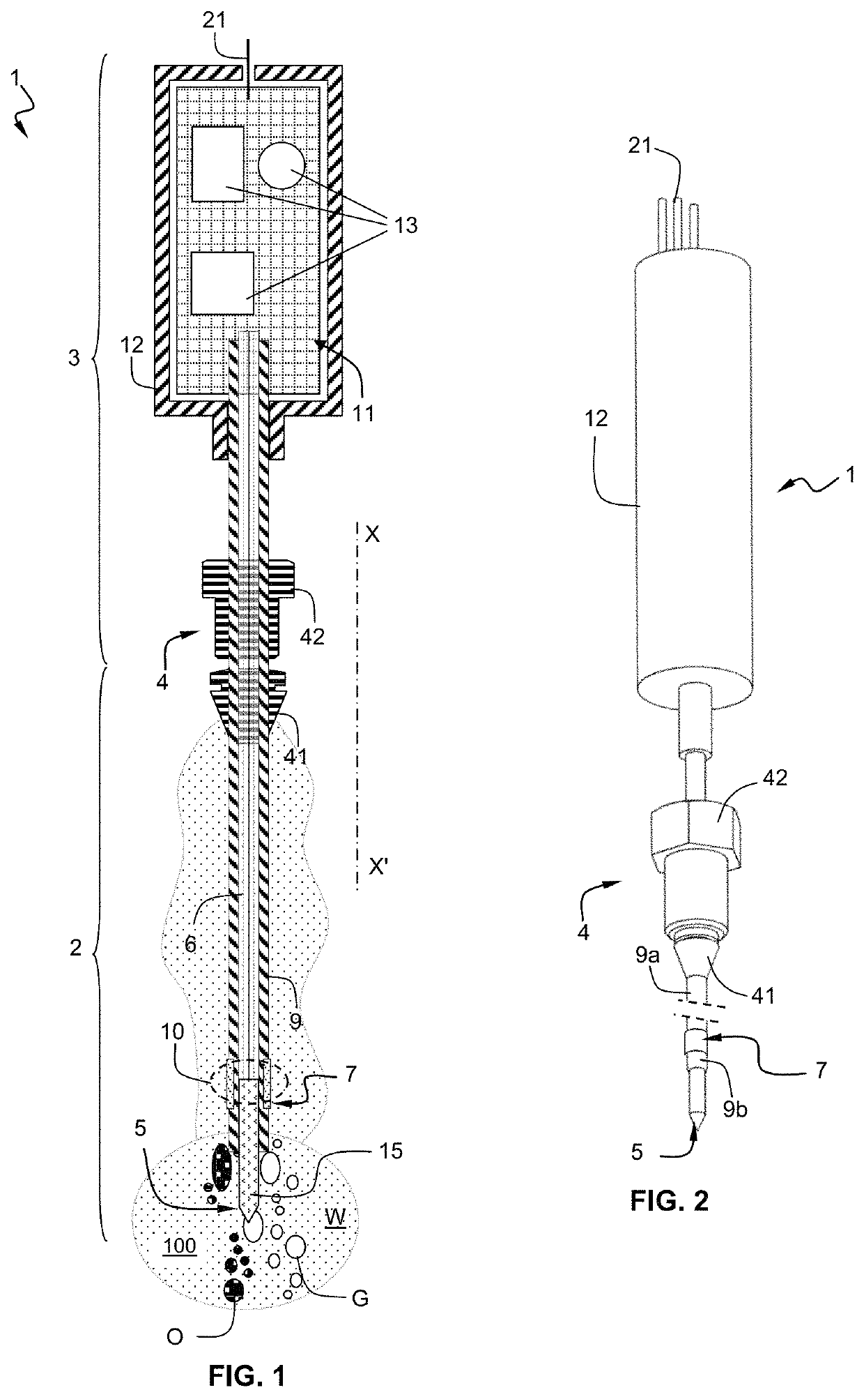
[0028]FIG. 1 is a partial cross-section view schematically illustrating a downhole fluid properties optical analysis probe 1.

[0029]The optical analysis probe 1 has the general shape of an elongated cylindrical body extending along the longitudinal axis XX′. The optical analysis probe 1 comprises a first portion 2 in contact with the well fluid 100 to be analyzed (i.e. in contact with harsh environments), and a second portion 3 separated from the fluid 100 to be analyzed (protected from harsh environments). A probe connector 4 separates the first portion 2 from the second portion 3.

[0030]In the first portion 2, an optical tip 5 is coupled to an optical link in the form of a single optical fiber (not depicted) or an optical fibers bundle 6 (e.g. optical fiber made of silica, fluoride glass, phosphate glass, chalcogenide glass, plastics, doped or not) that is i...


PUM

PropertyMeasurementUnit
diameteraaaaaaaaaa
temperatureaaaaaaaaaa
pressureaaaaaaaaaa

Abstract

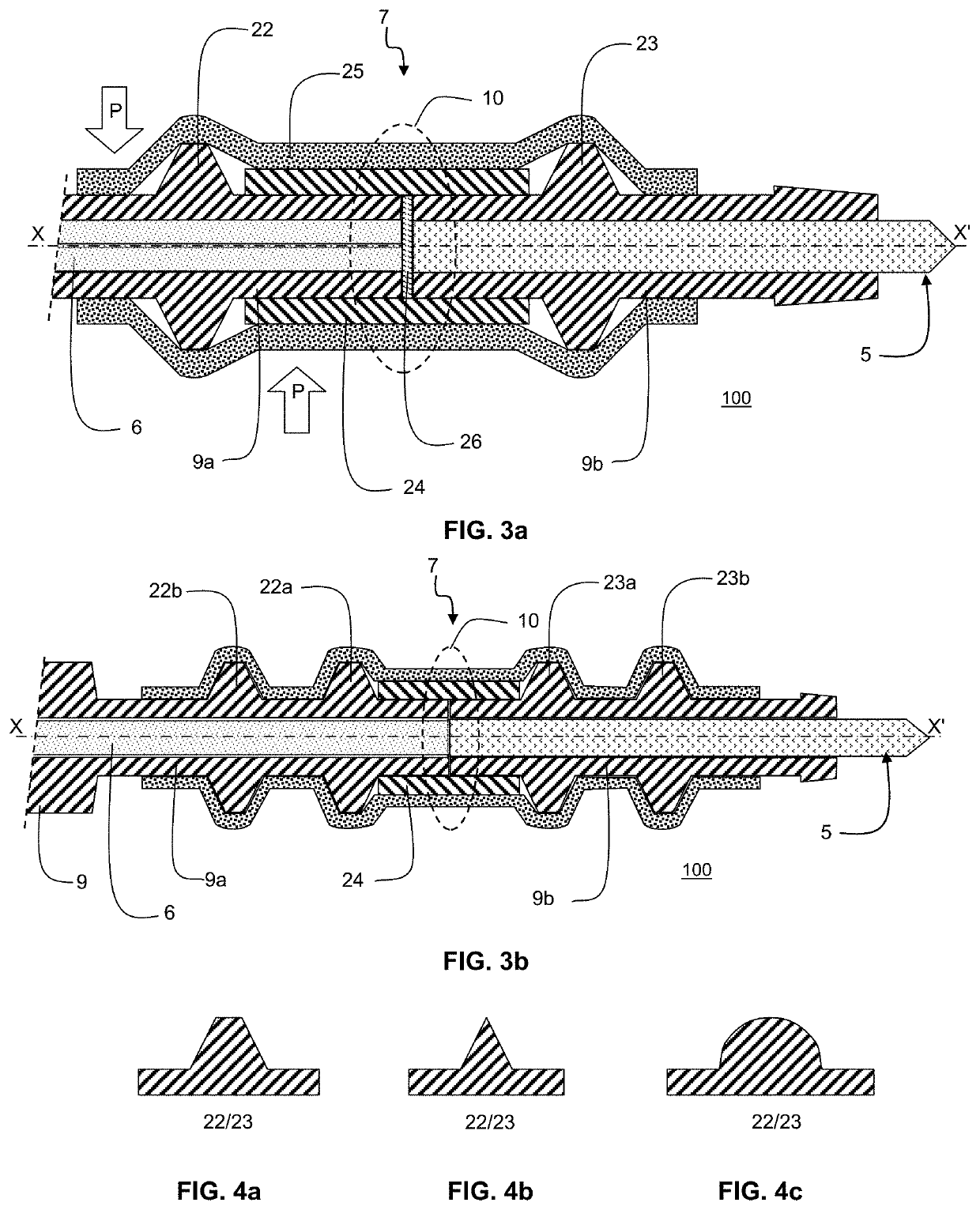
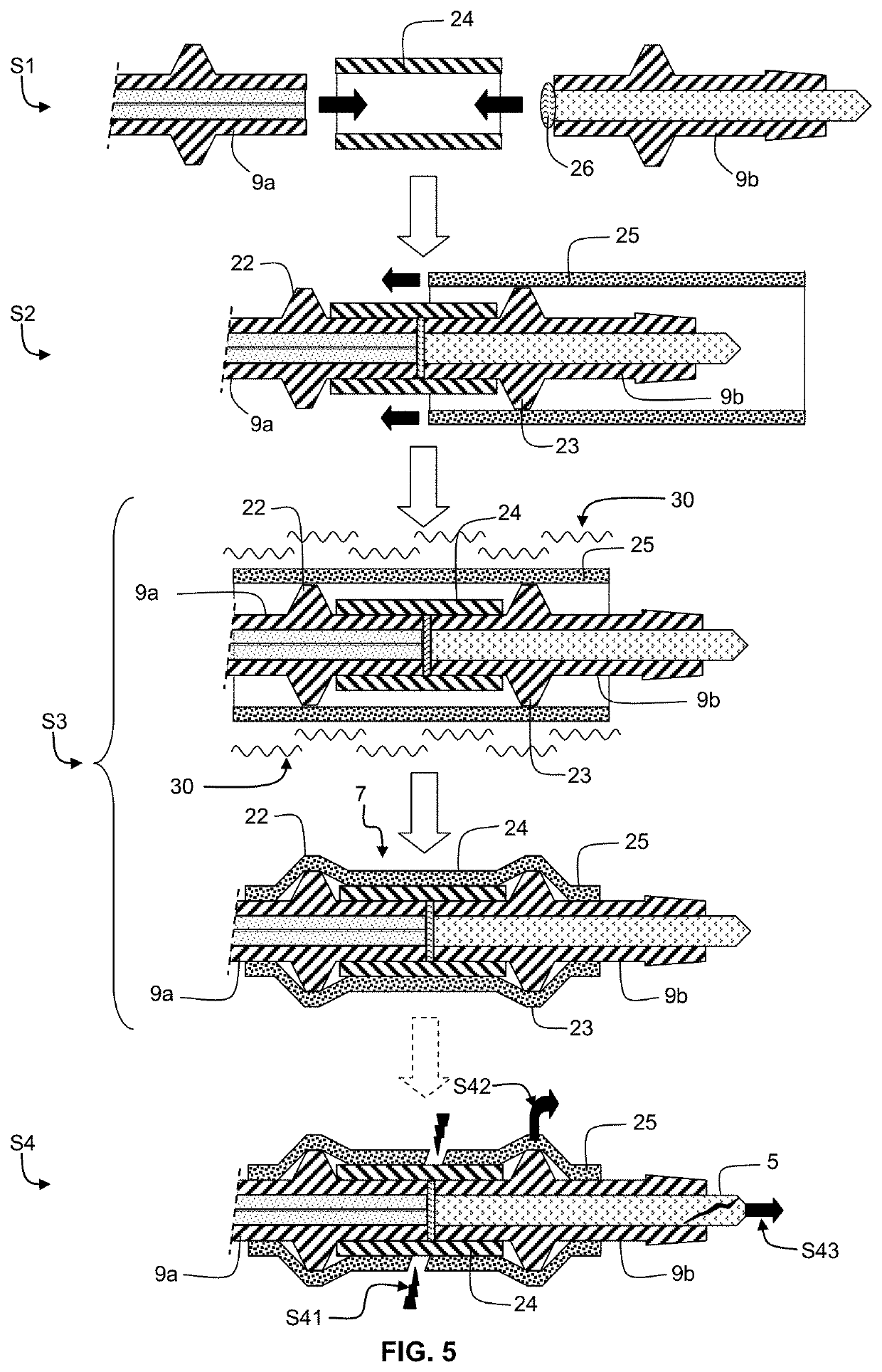
A downhole fluid properties optical analysis probe (1) to analyze at least one property of a multiphase flow mixture (100) flowing in a hydrocarbon well (51) has an elongated cylindrical body shape. It comprises an optical tip (5) at one end of the elongated cylindrical body arranged to be in contact with the multiphase flow mixture (100). It further comprises an optical link (6) adapted for a connection with an electronics module (11) at another end of the elongated cylindrical body arranged to be separated from the multiphase flow mixture (100). The optical tip (5) is coupled to the optical link (6) through a removable and watertight coupling (7). The removable and watertight coupling comprises a first portion (9a) of a protective tube (9) resistant to downhole conditions, said first portion (9a) enclosing the optical link (6) and comprising at least one first ring bulge (22) close to a coupling interface (10), and a second portion (9b) of the protective tube (9) partially enclosing the optical tip (5) such as to let a distal end of the optical tip (5) in contact with the multiphase flow mixture (100), said second portion (9b) comprising at least one second ring bulge (23) close to the coupling interface (10). It further comprises a coupling tube (24) surrounding facing ends of the first portion (9a) and the second portion (9b), said coupling tube (24) being adjusted in size to fit in between said first and second ring bulges (22, 23), and a coupling and protecting sheath (25) enclosing said first ring bulge (22), coupling tube (24) and second ring bulge (23) in a watertight manner.

Description

TECHNICAL FIELD[0001]The invention relates to an optical analysis probe measuring downhole fluid properties comprising a removable and watertight coupling for the optical tip. Such an optical analysis probe may be integrated in a downhole measuring tool like a production logging tool used to analyze a multiphase fluid mixture flowing from a hydrocarbon bearing zone into a hydrocarbon well. Such probes and tools operate at downhole pressure and temperature conditions.BACKGROUND[0002]During the evaluation or production of a hydrocarbon well, it is necessary to monitor various parameters for example the relative volumetric flow rates of the different phases (e.g. oil, gas and water) of the multiphase fluid mixture flowing into the pipe of the well from the hydrocarbon bearing zones, and / or to identify the phases.[0003]Optical analysis probes that are used within a downhole measuring tool operate in harsh environment, namely extreme conditions including high pressure from several hundre...

Claims


Application Information

Patent Timeline
Patent Type & Authority Patents(United States)
IPC IPC(8): G01V8/16E21B47/01G01N21/85G01N21/47E21B47/10G01N21/64G02B6/36G02B6/44E21B49/08E21B17/10
CPCE21B49/08G01V8/16G01N21/8507E21B47/011E21B47/102G01N21/474E21B17/1078G01N21/645G01N2021/4742G01N2021/8528G02B6/3624G01N2021/6484G02B6/4428E21B47/017E21B47/113
Inventor DONZIER, ERICABBASSI, LINDATAVERNIER, EMMANUEL
Owner OPENFIELD
Learn More