
Metal wire feeding system

a metal wire and wire feeding technology, applied in the field of metal wire feeding system, can solve the problems of limiting the accuracy of welding technique is usually too coarse to allow direct forming of objects with acceptable dimensions, and the output torque of the motor driving the rotation of the wire spool can be a limiting factor in the supply of wire, so as to achieve stable and reliable wire feeding speed and stable mass input rate

Active Publication Date: 2020-02-04
NORSK TITANIUM
View PDF22 Cites 0 Cited by
  • Summary
  • Abstract
  • Description
  • Claims
  • Application Information

AI Technical Summary

Benefits of technology

[0014]Another objective of the invention is to provide a method for rapid layered manufacturing of titanium or titanium alloy objects using a metal wire and one or more welding torches. This invention addresses the needs for an improved, economical method of performing direct metal deposition by providing systems and methods for delivery of metal wire to a plasma arc of a welding torch at a desired location with respect to the plasma arc, which can result in an increased rate of deposition of metal in solid freeform fabrication. This invention further addresses the need for a method of increasing throughput and can produce distortion-free direct metal deposition-formed parts with smooth, near net shaped deposition boundaries.
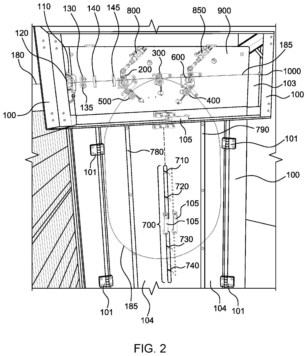
[0016]The wire feeding systems provided herein can include a control system responsive to the sensor(s) to modulate the supply of additional wire from the wire source into the cabinet thereby modulating the size of the loop of slack wire and thus the amount of slack wire within the cabinet.
[0026]In the metal wire feeding systems provided herein, the frictionally enhanced surface of the grooves of rollers 220, 205, 620 and 605 can include protrusions on the surface. The frictionally enhanced surface of the grooves can increase the frictional forces between the grooves and the wire that passes through the grooves. The enhanced frictional forces can decrease slippage between the wire and the grooves. In the metal wire feeding systems provided herein, the motor 225 and the motor 625 each separately can be a direct-current motor driven by a power control signal and a stepper motor.
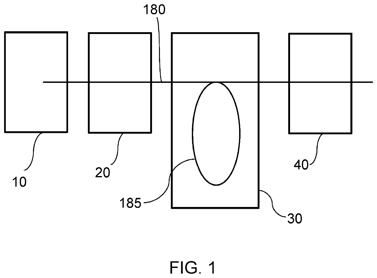
[0038]In the metal wire feeding systems provided herein, the combination of three or more wire guides permits the metal wire 180 to bend to form a loop of slack wire 185 from the metal wire 180 in a way that does not result in a permanent deformation in the metal wire 180.
[0039]Also provided are methods of providing a metal wire to a plasma arc of a welding torch. The methods include the steps of providing a cabinet to receive the metal wire; feeding a sufficient amount of the metal wire from a wire supply source into the cabinet to form a loop of slack wire; feeding an amount of slack wire from the loop of slack wire to the plasma arc of a welding torch; and supplying additional metal wire from the wire supply source to compensate for the slack wire fed to the plasma arc of the welding torch to maintain a loop of slack wire. The amount of wire supplied from the wire supply source generally is sufficient to maintain the loop of slack wire to allow for a continuous delivery of slack wire to the plasma arc of the welding torch. The loop of slack wire within a cabinet is maintained in the proper position so that the metal wire continuously can be fed to the plasma arc of the welding torch and maintained at a predetermined position within the plasma arc of the welding torch. This secures a stable and reliable wire feed speed, providing for a stable mass input rate in the deposition process. Instability in metal wire supply can lead to unstable deposition, and also can result in burn-back of the wire and stopping production. The loop of slack wire allows the feeding of the metal wire from the wire supply source into the cabinet to be independent of pulling an amount of slack wire from the loop of slack wire to feed to the plasma arc of the welding torch. The loop of slack wire acts as a buffer between the tension unit that feeds metal wire from the supply source into the cabinet and the slack wire pulling unit that pulls slack wire from the loop to feed it to the plasma arc.

Problems solved by technology

These techniques have a disadvantage of high material waste of the expensive titanium metal and large lead times in the fabrication of the metal part.
The accuracy of the welding technique is usually too coarse to allow directly forming the object with acceptable dimensions.
The output torque of motors driving rotation of the wire spool can be a limiting factor in providing wire at a steady state, particularly from a fully loaded spool.
The rotational inertia of the wire on the spool can limit the speed and acceleration rate at which the wire can be unwound off of the spool to be delivered to the welding torch.
Slippage can result in deformation of the wire, and also creating a deviation in the desired position and angle of the wire relative to the plasma arc.
Slippage also limits the operating speed of the fabricating equipment.
If the variation in wire feed speed or acceleration of the wire at the wire source results in too much tension between the wire source and the feeder rollers and pulleys that deliver the wire to the plasma arc of the welding torch, the increased tension can result in the formation a kink, bend or other deformation in the wire.
High tension also can result in metal wire being pulled back toward the wire source, which would prevent feed of metal wire to the welding electrode, resulting in an unwanted discontinuous deposition layer, or an unintended hole or gap in the layer being deposited on the freeform object being made.
If the tension is too low, an excess of slack wire can result.
The excess wire can become entangled with itself or a part of the machinery, which can cause bends or kinks in the wire, making it difficult or impossible to correctly position the wire relative to the plasma arc.
In addition, unwinding of the wire from the spool results in changes in the position of the wire as it leaves the spool due to the coiled nature of the wire on the spool.
At higher rates of use, the horizontal and vertical position of the wire rapidly can change, which can result in slippage from the rollers, guiding wheels or clamping devices used to deliver the wire to the welding torch.

Method used


Image

  • Metal wire feeding system
  • Metal wire feeding system
  • Metal wire feeding system

Examples


Embodiment Construction

A. Definitions

[0055]Unless defined otherwise, all technical and scientific terms used herein have the same meaning as is commonly understood by one of skill in the art to which the inventions belong. All patents, patent applications, published applications and publications, websites and other published materials referred to throughout the entire disclosure herein, unless noted otherwise, are incorporated by reference in their entirety. In the event that there are a plurality of definitions for terms herein, those in this section prevail. Where reference is made to a URL or other such identifier or address, it is understood that such identifiers can change and particular information on the internet can come and go, but equivalent information can be found by searching the internet. Reference thereto evidences the availability and public dissemination of such information.

[0056]As used here, the singular forms “a,”“an” and “the” include plural referents unless the context clearly dictat...


PUM

PropertyMeasurementUnit
diameteraaaaaaaaaa
voltageaaaaaaaaaa
currentaaaaaaaaaa

Abstract

Provided are a systems and methods for continuously providing a metal wire to a welding torch for manufacturing objects by solid freeform fabrication to provide continuous deposition of metal to the freeform object, especially objects made with titanium or titanium alloy wire.

Description

FIELD OF THE INVENTION[0001]The present invention relates to a system and method of feeding metal wire for manufacturing objects by solid freeform fabrication, especially objects made from titanium and titanium alloy wire.BACKGROUND OF THE INVENTION[0002]Structured metal parts made of titanium or titanium alloys are conventionally made by casting, forging or machining from a billet. These techniques have a disadvantage of high material waste of the expensive titanium metal and large lead times in the fabrication of the metal part.[0003]Fully dense physical objects may be made by a manufacturing technology known as rapid prototyping, rapid manufacturing, layered manufacturing, solid freeform fabrication, additive fabrication, additive manufacturing or 3D printing. This technique employs computer aided design software (CAD) to first construct a virtual model of the object which is to be made, and then transform the virtual model into thin parallel slices or layers, usually horizontall...

Claims


Application Information

Patent Timeline
Patent Type & Authority Patents(United States)
IPC IPC(8): B23K9/133B23K26/342B23K9/04B23K15/00B33Y40/00B23K103/14
CPCB23K26/342B23K9/044B23K9/133B23K15/0006B33Y40/00B23K2103/14B23K9/1333B65H49/32B65H49/325B65H51/10B65H59/387B65H2701/36B21F23/00Y02P10/25B23K9/1336
Inventor FORSETH, TRONDVIGDAL, BREDEFALLA, TOM-ERIKROLSTAD, DYRERAMSLAND, ARNE
Owner NORSK TITANIUM
Learn More