Optical sensing apparatuses, method, and optical detecting module capable of estimating multi-degree-of-freedom motion

a technology of optical sensing apparatus and optical detecting module, which is applied in the direction of navigation instruments, instruments, image enhancement, etc., can solve the problems of complex implementation of above-mentioned conventional systems, easy loss of tracking solutions, etc., and achieves less computational intensive, less complex implementation or computation, and compact

Active Publication Date: 2020-02-18
PIXART IMAGING INC
View PDF3 Cites 0 Cited by
  • Summary
  • Abstract
  • Description
  • Claims
  • Application Information

AI Technical Summary

Benefits of technology

[0010]According to the embodiments, compared to the conventional tracking solutions, the invention is potentially both more compact and less computationally intensive than the conventional tracking solutions. In the embodiments, a multi-zone scene processing with a single type of processing engine is used to compute motion in six-degree-of-freedom motion. The advantage or distinguishing feature of this invention includes: less complex implementation or computation as it only uses cross-correlation to detect all 6-DOF motion. Also, it is not susceptible to objects moving out of the field of view as it tracks the overall scene and not specific objects. Also, it is more compact as it does not require significant separation of image sensors. Also, it is more cost effective as it require only a simple hardware / opto-mechanical configuration.

Problems solved by technology

However, the above-mentioned conventional systems are very complicated for implementation since it is necessary to different and very complex processing methodology or algorithm for the translational, rotation and depth sensing respectively.
However such tracking solution inevitably requires two image sensors with a significant positional separation to work well, in addition to requiring complex imaging processing and comparison.
In addition to the complex computation required, the solution is also susceptible to loss of tracking when the object moves out of the field of view of the sensor.

Method used


Image

  • Optical sensing apparatuses, method, and optical detecting module capable of estimating multi-degree-of-freedom motion
  • Optical sensing apparatuses, method, and optical detecting module capable of estimating multi-degree-of-freedom motion
  • Optical sensing apparatuses, method, and optical detecting module capable of estimating multi-degree-of-freedom motion

Examples


Embodiment Construction

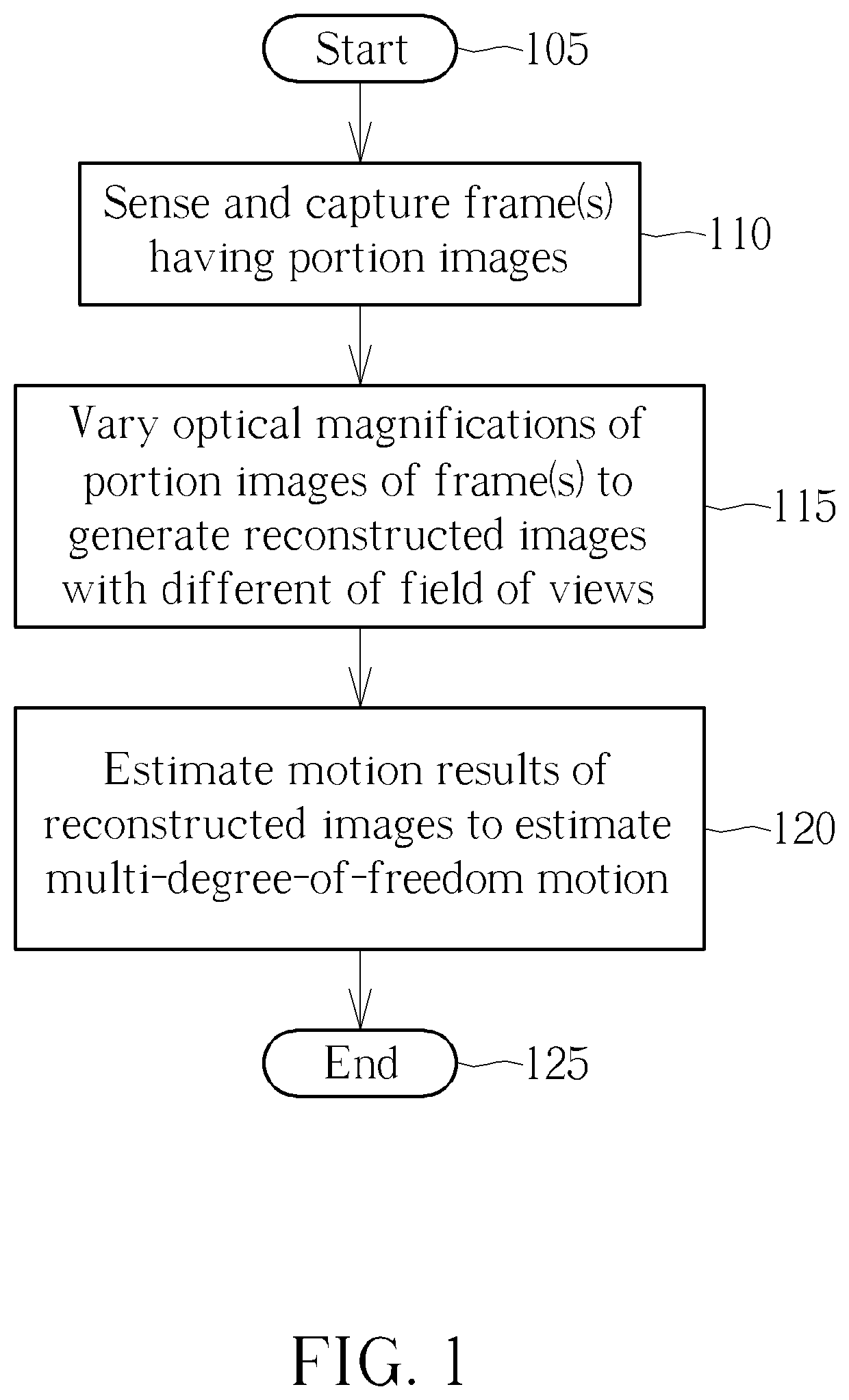
[0036]The invention is to provide a method for tracking multi-degree-of-freedom motion of an object. For example, the invention is to track six-degrees-of-freedom motion, i.e. translation motions along X-axis, Y-axis, and Z-axis as well as rotations along the X-axis, Y-axis, and Z-axis.

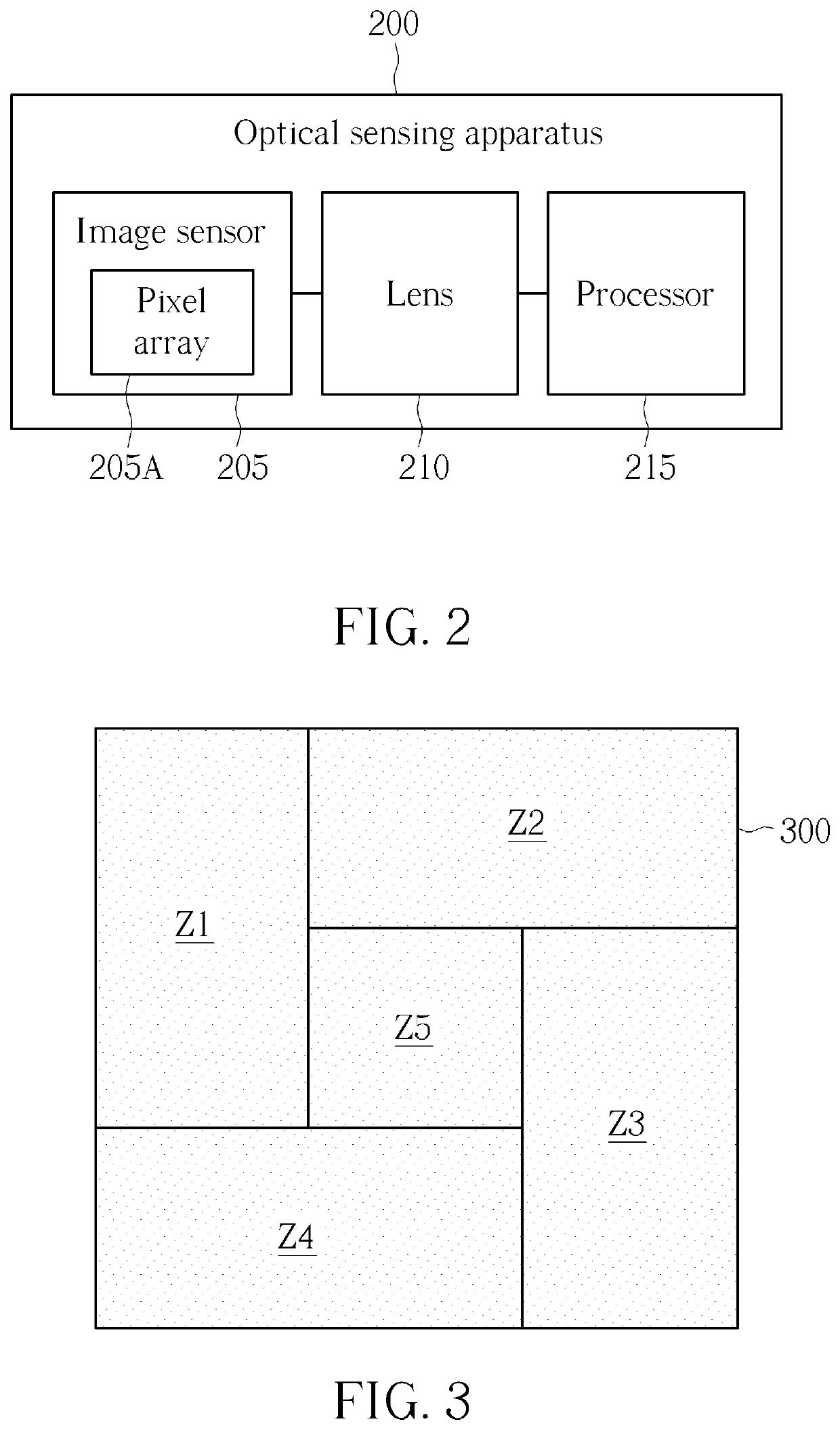
[0037]Refer to FIG. 1 in conjunction with FIG. 2. FIG. 1 is a diagram illustrating a flowchart of a method capable of estimating multi-degree-of-freedom motion of an optical sensing apparatus according to embodiments of the invention. The method is applied to the optical sensing apparatus such as a wearable electronic device which is for example a head-mounted device (e.g. a virtual reality (VR) head-mounted display device (but not limited)). In another embodiment, the optical sensing apparatus can be an Unmanned Aerial Vehicle (UAV) device or an Unmanned Aircraft System (UAS) device. FIG. 2 is a block diagram of an example of the optical sensing apparatus 200. Provided that substantially the same res...


PUM


Abstract

A method capable of estimating multi-degree-of-freedom motion of an optical sensing apparatus includes: providing an image sensor having a pixel array having a plurality of image zones to sense and capture a frame; providing and using a lens to vary optical magnifications of a plurality of portion images of the frame to generate a plurality of reconstructed images with different of field of views, the portion images of the frame respectively corresponding to the image zones; and estimating and obtaining a motion result for each of the reconstructed images to estimate the multi-degree-of-freedom motion of the optical sensing apparatus.

Description

BACKGROUND OF THE INVENTION1. Field of the Invention[0001]The invention relates to a multi-degree-of-freedom motion mechanism, and more particularly to optical sensing apparatuses, method, and optical detecting module which are capable of estimating multi-degree-of-freedom motion.2. Description of the Prior Art[0002]Generally speaking, a conventional tracking solution such as optical mouse typically tracks only two degrees of freedom motion (translations along X-axis and Y-axis). This may be expanded to track rotational motion in the X-Y plane (i.e. along the Z-axis) for a three-degree-of-freedom (3-DOF) motion estimation system. Further, another conventional tracking solution may also include depth sensing via a time-of-flight or structured light operation / system. With this additional depth sensing, translational motion along the Z-axis and rotational motions along X-axis and Y-axis can be tracked. However, the above-mentioned conventional systems are very complicated for implement...

Claims


Application Information

Patent Timeline
Patent Type & Authority Patents(United States)
IPC IPC(8): G01P13/02G06T7/20G01C23/00G01S3/00H04N5/232
CPCH04N5/232H04N5/23296G06T7/20G01P13/02G01S3/00G01C23/00G06T2207/20021G06T2207/30244G06F3/011G06F3/0346G06T3/0018G06T2207/10021G01S5/16H04N23/60H04N23/69
Inventor LEE, SAI MUN
Owner PIXART IMAGING INC
Why Eureka
Try Eureka