
System for optical linear sampling and coherent detection of an optical signal

a linear sampling and optical signal technology, applied in optics, instruments, electrical equipment, etc., can solve the problems of inability to accurately detect the one-bit delay must be readjusted to the binary bitrate and the poor quality of the input optical signal no longer has any impact on the output optical signal

Active Publication Date: 2020-03-17
ALCATEL LUCENT SAS
View PDF7 Cites 0 Cited by
  • Summary
  • Abstract
  • Description
  • Claims
  • Application Information

AI Technical Summary

Benefits of technology

[0006]The goal of the proposed solution is to eliminate the aforementioned drawbacks, namely the need to have a one-bit optical delay adjustable with the bitrate of the input signal for the first solution, or the inability to measure unknown signals for the other station.
[0014]According to one aspect, a thermal device makes it possible to tune the optical filter.
[0015]According to another aspect, an electrical adjustment device makes it possible to tune the optical filter.
[0018]According to one variant, the optical amplifier is a semiconductor optical amplifier SOA operating within its saturation regime in order to mitigate parasitic modulation on the optical signal at the output of the tunable optical filter.
[0030]This solution is advantageous for optimal linear sampling OLS, with improved flexibility in monitoring advanced-format optical signals, and also a more flexible solution for coherent transmission systems.

Problems solved by technology

Although it is possible to implement a high-quality optical local oscillator (with greater costs), the input optical signal has no reason to be high-quality, because most of the time the optical signal OS, which the OLS systems must measure, is unknown.
One possible route is improving OLS systems such that the poor quality of the input optical signal no longer has any impact on the resulting output optical signal.
One of the main drawbacks of the solution is that the one-bit delay must be readjusted to the binary bitrate of the input optical signal.
This therefore limits its practical application, unless automated detection of the binary bitrate is implemented, and the one-bit delay is automatically readjusted.
However, in this solution, no readjustment of the delay is performed.
The primary drawback of this solution is that it is not appropriate for measurement of any unknown input optical signal by the OLS technique, because the modulated optical signal is produced within the experimental device.

Method used


Image

  • System for optical linear sampling and coherent detection of an optical signal
  • System for optical linear sampling and coherent detection of an optical signal
  • System for optical linear sampling and coherent detection of an optical signal

Examples


Embodiment Construction

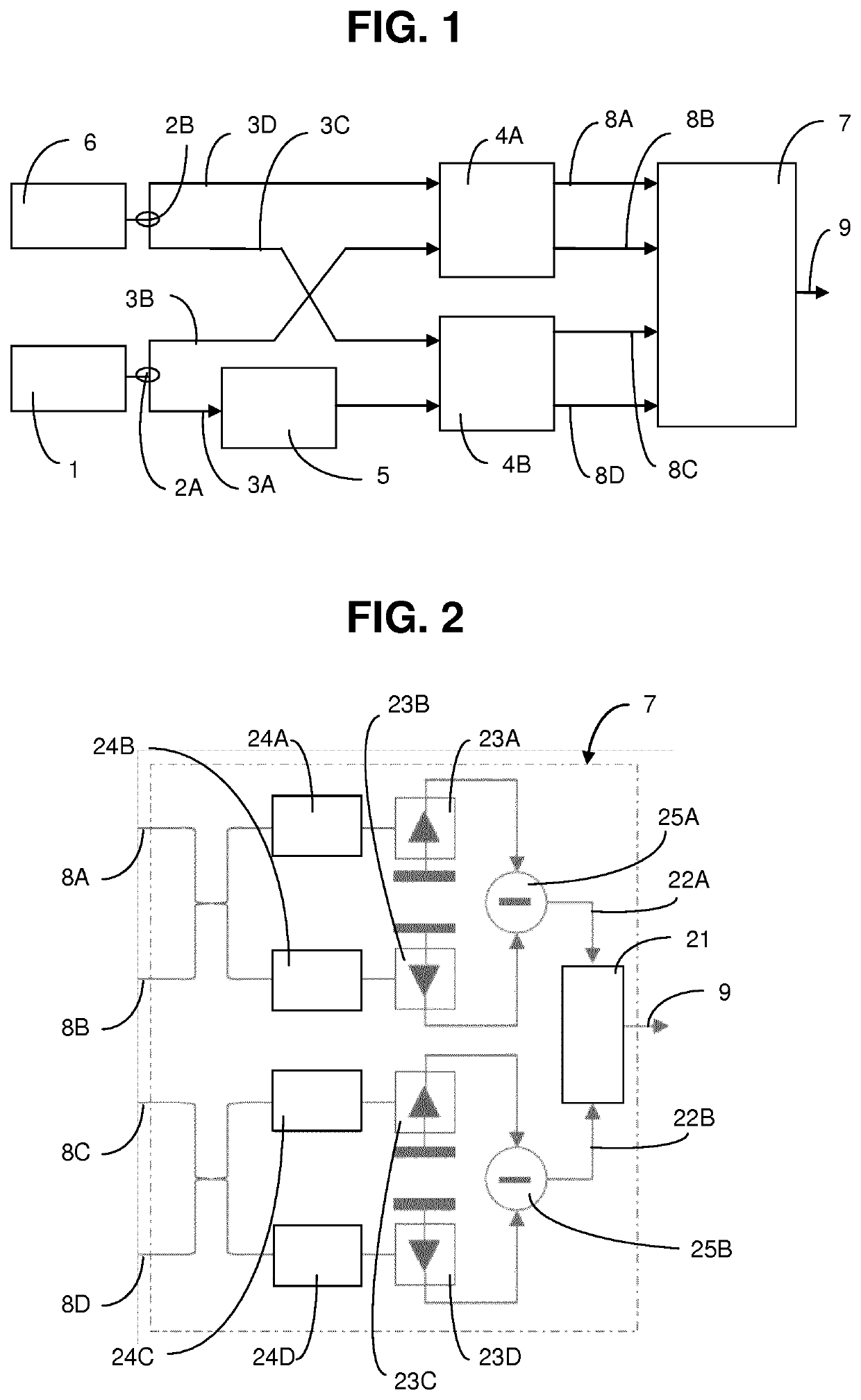
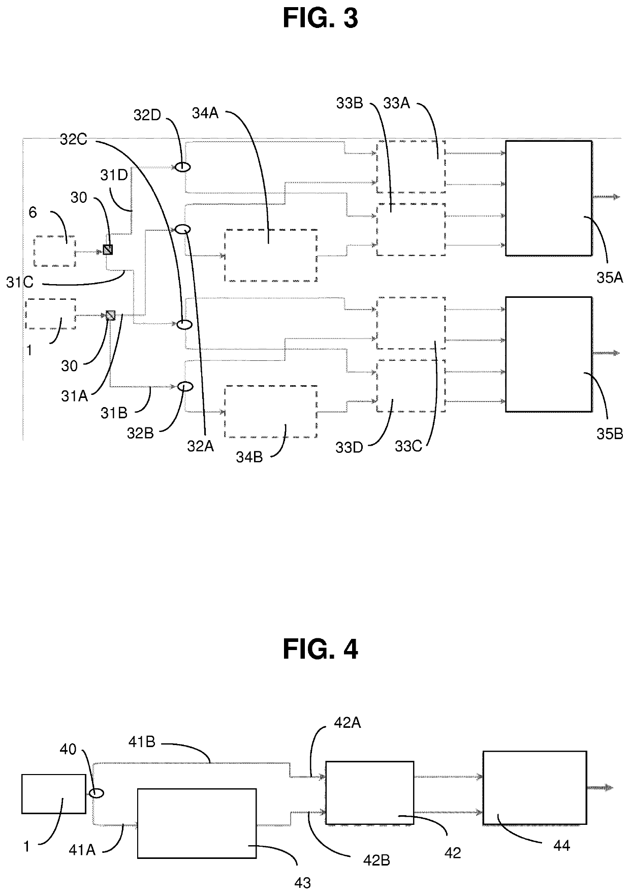
[0044]FIG. 1 depicts one partial embodiment of a system for linear optical sampling of very high-speed complex optical signals OS (phase- and / or amplitude-encoded). In reality, the input optical signal OS propagates using an unknown mode. The incoming optical signal OS is therefore projected into the system using two arbitrary linear propagation modes. In this illustration, a single polarization mode, such as the transverse electric mode TE of the incident vector optical signal OS, is sampled and processed by the optical linear sampling system.

[0045]At a first input 1 of the optical linear sampling system, the optical signal OS that carries data is split into two identical replicas by an optical coupler 2A which are sent on two optical paths and is transported by a polarization-maintaining optical fiber PMF 3A, 3B. Here, signal splitting means producing two identical replicas that each have half the power of the incoming signal. A replica of the modulated optical signal that carries...


PUM

PropertyMeasurementUnit
central wavelengthaaaaaaaaaa
opticalaaaaaaaaaa
wavelengthaaaaaaaaaa

Abstract

A system for optical linear sampling and coherent detection of an optical signal OS comprises a source emitting a pulsed optical signal SP and an optical coupler that splits the pulsed optical signal SP into two replicas, the first replica of the pulsed optical signal SP is sent to a first optical hybrid circuit and the second replica of the pulsed optical signal SP is send to a second optical hybrid circuit, a source emitting an optical signal OS and optical coupler that splits the incoming optical signal OS into two replicas, the first replica of the incoming optical signal OS is sent to the first optical hybrid circuit and the second replica of the incoming optical signal OS is sent to a wavelength recovery device WVLR, whose output is a continuous-waveform optical signal CW at the central wavelength of the incoming optical signal OS, which sends it to the second optical hybrid circuit. such that the optical signal OS is sampled within the first hybrid circuit and the continuous waveform optical signal CW is sampled in the second hybrid circuit, and a device BDADC comprising balanced photodectors detecting optical signals at the output of the two optical hybrid circuits and an analog / digital converter ADC.

Description

FIELD[0001]The present invention pertains to the field of optical network telecommunications, and more specifically to systems for linear optical sampling or coherent detection of complex optical signals, at high speed and with advanced encoding formats, which are used in diagnostic and surveillance equipment.BACKGROUND[0002]A high-quality optical local oscillator OLO or a high-quality optical signal are necessary in methods or devices used for optical linear sampling OLS. The quality of the optical local oscillator OLO and the optical signal may be measured in terms of optical spectral line width. The quality of such an optical signal may also be measured in an equivalent fashion by its coherence time. The best-quality optical signals have a narrower line width or a longer coherence time. Although it is possible to implement a high-quality optical local oscillator (with greater costs), the input optical signal has no reason to be high-quality, because most of the time the optical s...

Claims


Application Information

Patent Timeline
Patent Type & Authority Patents(United States)
IPC IPC(8): H04B10/61G02F1/21H04B10/64G01J11/00
CPCG01J11/00G02F1/21H04B10/614H04B10/615G02F2001/213G02F2001/212G02F1/212G02F1/213
Inventor SHEN, ALEXANDREPROVOST, JEAN-GUY
Owner ALCATEL LUCENT SAS
Learn More