
Negative electrode for lithium ion secondary battery and lithium ion secondary battery

a secondary battery and lithium ion technology, applied in the manufacture of final products, cell components, electrochemical generators, etc., can solve the problems of insufficient achieve prevent precipitation of li, and excellent input and output characteristics.

Active Publication Date: 2020-04-07
TDK CORPARATION
View PDF21 Cites 1 Cited by
  • Summary
  • Abstract
  • Description
  • Claims
  • Application Information

AI Technical Summary

Benefits of technology

The invention relates to a lithium ion secondary battery with a negative electrode that prevents the precipitation of Li and has excellent input and output characteristics. The technical effect is that the negative electrode prevents the precipitation of Li, which allows for the use of an improved lithium ion secondary battery with better performance.

Problems solved by technology

However, in the inventions disclosed in Patent Documents 1 and 2, sufficient input and output characteristics were not obtained.

Method used


Image

  • Negative electrode for lithium ion secondary battery and lithium ion secondary battery

Examples


example 1

[0108]A commercially available artificial graphite was used as a raw material, and the raw material was pulverized using a planetary ball mill (model PM200 manufactured by Retsch Co. Ltd.) at a rotational speed of 500 rpm of the planetary ball mill. Then, a particle size distribution was adjusted using an air classifier, and D10, D50, and D90 were set to 2 μm, 18 μm, and 42 μm in that order. Here, D10, D50, and D90 were a particle size (particle diameter) at an accumulation of 10%, a particle size at an accumulation of 50%, and a particle size at an accumulation of 90%, respectively, in a particle size distribution curve with a horizontal axis that represents a particle size and a vertical axis that represents cumulative %.

[0109]Next, a mechanochemical treatment was performed on the obtained pulverized raw material using a Mechanofusion (manufactured by Hosokawa Micron Co. Ltd.). That is, three forces: compressive stress, shear stress, and impact, were applied. In this case, a load ...

examples 10 to 17

[0120]In Example 10, a 0.1% sodium carboxymethyl cellulose (CMC) solution was sprayed onto carbon particles obtained under the same conditions as in Example 9 so that an adhesion amount thereof was 4% with respect to the weight of the carbon particles. Next, a negative electrode was obtained under the same conditions as in Example 9 except that carbon particles obtained by heating carbon particles to which CMC was adhered at 1000° C. in an inert atmosphere (surface-treated carbon particles) were used.

[0121]Examples 11 to 17 differed from Example 10 only in that adhesion amounts of a 0.1% CMC solution with respect to the weight of carbon particles were different.

examples 18 to 20

[0122]In Example 18, in a particle size distribution (particle sizes of D10, D50, and D90) of carbon particles obtained under the same conditions as in Example 9, particle sizes of D10, D50, and D90 were adjusted to 4 μm, 17 μm, and 32 μm using an air flow type classifier.

[0123]Examples 19 and 20 differed from Example 18 only in adjustment of the particle size distribution.


PUM

PropertyMeasurementUnit
pore size distributionaaaaaaaaaa
pore sizeaaaaaaaaaa
pore sizeaaaaaaaaaa

Abstract

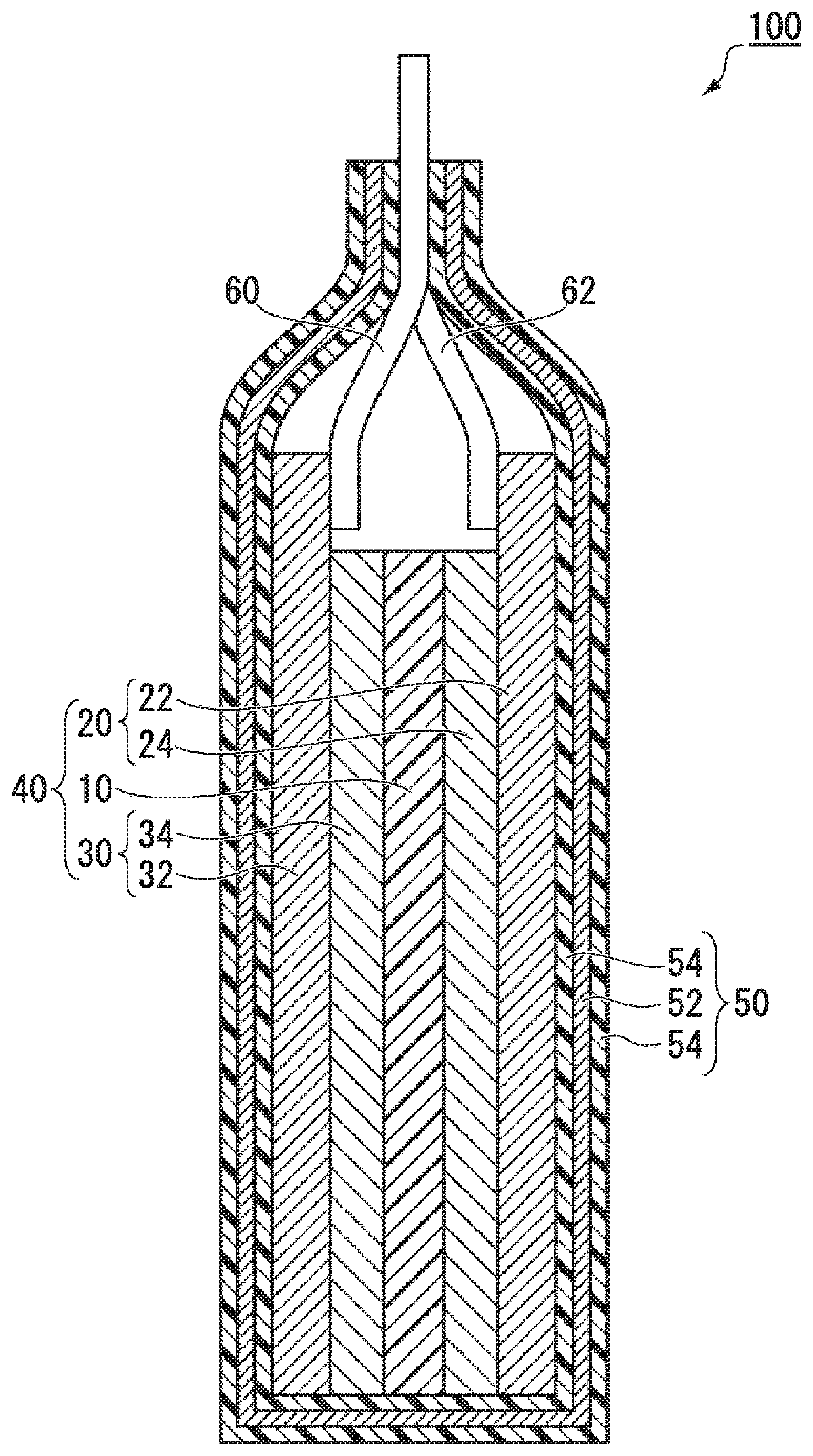
A negative electrode of a lithium ion secondary battery of the present invention includes a current collector (32) and a negative electrode active material layer (34) provided on the current collector (32). In the negative electrode of a lithium ion secondary battery, the negative electrode active material layer (34) includes carbon particles, a degree of graphitization of the carbon particles is 1.0 or more and 1.5 or less and a degree of orientation of the carbon particles is 50 or more and 150 or less; where, the degree of graphitization is a ratio (P101 / P100) between a peak intensity P101 of the (101) plane and a peak intensity P100 of the (100) plane in an X-ray diffraction pattern and the degree of orientation is a ratio (P002 / P110) between a peak intensity P002 of the (002) plane and a peak intensity P110 of the (110) plane in an X-ray diffraction pattern.

Description

BACKGROUND OF THE INVENTIONField of the Invention[0001]The present invention relates to a negative electrode of a lithium ion secondary battery and a lithium ion secondary battery.[0002]Priority is claimed on Japanese Patent Application No. 2017-052694, filed Mar. 22, 2017, and Japanese Patent Application No. 2018-008465, filed Jan. 22, 2018, the content of which is incorporated herein by reference.Description of Related Art[0003]Lithium ion secondary batteries are lighter and have a higher capacity than nickel-cadmium batteries, nickel hydride batteries, and the like, and are widely used as power sources for portable electronic devices. In addition, lithium ion secondary batteries are strong candidates for power sources for hybrid vehicles and electric vehicles. The demand for reducing the size of portable electronic devices, high functionality, and a high capacity of power sources for vehicles is increasing year after year, and a higher capacity of lithium ion batteries is expecte...

Claims


Application Information

Patent Timeline
Patent Type & Authority Patents(United States)
IPC IPC(8): H01M4/133H01M10/0525H01M4/587H01M4/38H01M4/02H01M10/0585
CPCH01M10/0525H01M4/38H01M4/133H01M4/587H01M10/0585H01M2004/027Y02E60/10Y02P70/50
Inventor SASAGAWA, HIROSHIKAWANAKA, YASUYUKIAOKI, TAKUYA
Owner TDK CORPARATION
Learn More