Perforated piezoelectric hydrophone, array comprising a plurality of hydrophones and method for making said hydrophone

a piezoelectric hydrophone and piezoelectric hydrophone technology, applied in the field of sonar, can solve the problems of poor hydrostatic sensitivity, low mechanical coupling, and limited noise level at the beamforming output, and achieve the effect of simple and inexpensive, and ensure the pressure resistance of the devi

Active Publication Date: 2020-05-05
THALES SA
View PDF5 Cites 0 Cited by
  • Summary
  • Abstract
  • Description
  • Claims
  • Application Information

AI Technical Summary

Benefits of technology

[0014]The provided solution consists in improving the multilayer hydrophone with uniform piezoelectric plates by modifying its design. More specifically, it is based on making perforations in the layers of piezoelectric material. These perforations are filled with a filler material which may be a solid material or a fluid, for example a gas or even vacuum. The piezoelectric material of the layer, connected along three directions, and the filler material, connected only in the direction of stacking, form a piezocomposite with 3-1 connectivity. A function of the perforations is to provide lateral decoupling in the direction perpendicular to the perforations, thus allowing the piezoelectric material to operate in a more favorable mode than in a multilayer sensor with uniform plates and allowing the sensitivity of the sensor to be improved. Furthermore, the perforations provide a stress amplification effect in the direction of stacking by virtue of the ratio of the areas of the rigid layers to those of the layers of piezoelectric material, which is added to the preceding effect and allows the sensitivity of the sensor to be enhanced further still.
[0032]a greater possibility for the fraction of filler material per unit volume to be adjusted with perforated PVDF, allowing the sensitivity / capacitance trade-off to be adjusted.

Problems solved by technology

Their sensitivity in hydrostatic mode, i.e. when the normal stresses are identical in three directions, is generally poor.
In the sensor, bending modes exist in the useful band but they exhibit very low mechanical coupling due to the twin layer assembly, i.e. an assembly in which the piezoelectric layer is sandwiched between two electrodes.
However, since the various forms of self-noise (noise radiated by the hydrophone-bearing structure or support, noise due to the direct flow of water against the hydrophone) decrease rapidly with frequency, the noise level at the beamforming output becomes limited by the electrical noise of the hydrophone channel, which makes it necessary to produce electroacoustic transducers having the lowest possible electrical noise.
Specifically, this type of coating decreases the mechanical noise level at the beamforming output further still, which noise is the main contributor to self-noise when the hydrophone is fixed or moving at low speed.
However, the main problem of the multilayer elementary sensor with uniform piezoelectric plates resides in the fact that the dielectric losses of the PVDF material increase substantially with frequency, resulting in an increase in the electrical noise of the elementary sensor.
However, this solution does not allow the requirement in terms of angular coverage of the array at the highest frequencies to be met, since this requirement involves a decrease in the area of the elementary sensor.
Furthermore, it does not allow a constraint to be met on the integration of the sensor within a given volume of thickness, which does not allow the thickness of the PVDF material to be increased indefinitely for the purpose of improving the sensitivity or the capacitance of the elementary sensor.
However, no additional improvement is observed in blocked mode, mainly due to the high Poisson's ratio.
These materials make it possible to decrease the electrical noise of the sensor by a few dB for a given volume, but with a corresponding increase in the supply cost.
Furthermore, the static pressure resistance of porous PVDF is limited and its properties are irreversibly degraded above 70 bar.
Unfortunately, in this type of composite, the filler material is exposed to static pressure on the lateral faces of the plate.
The choice of filler material therefore results from a trade-off between performance and resistance to submersion, i.e. between low stiffness and high yield strength.
Relatively rigid and resistant polymers are therefore typically used, which limits the potential sensitivity gain and restricts the field of application to rigid piezoelectric materials (ceramics or piezoelectric single crystals).
1-3 composites allow the electrical noise of the sensor to be substantially decreased but provide mediocre sensitivity at a given thickness, which tends to have a negative impact on the electrical noise of the entire channel (then chiefly dominated by the noise of the pre-amplification chain).
However, the configurations explored until now suffer from the same limitations, due to the fact that the filler material is still in communication with the exterior and subjected to static pressure.

Method used


Image

  • Perforated piezoelectric hydrophone, array comprising a plurality of hydrophones and method for making said hydrophone
  • Perforated piezoelectric hydrophone, array comprising a plurality of hydrophones and method for making said hydrophone
  • Perforated piezoelectric hydrophone, array comprising a plurality of hydrophones and method for making said hydrophone

Examples


Embodiment Construction

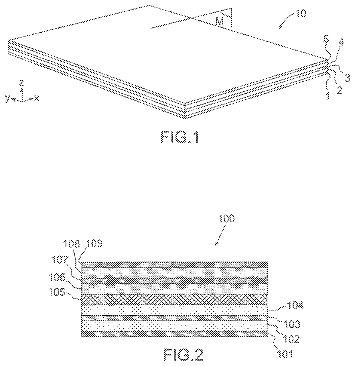
[0063]The invention relates to a hydrophone configured to operate in push-pull mode. This type of hydrophone is designed to be subjected to the same pressure on all faces thereof. It is therefore configured to have an operating frequency domain in which its size is much smaller than the wavelength of the acoustic waves detected.

[0064]This type of hydrophone is in contrast to hydrophones intended to operate by flexing, such as the hydrophones referred to as cantilever beam hydrophones that are intended to detect differences in pressure between their opposite faces.

[0065]The hydrophone according to the invention may be intended to be submerged at great depth. In this case, it must resist high hydrostatic pressures, for example at least 30 bar.

[0066]FIG. 1 shows a schematic representation in perspective of an example of a hydrophone according to the invention. This hydrophone comprises a stack 10 of layers 1 to5, for example assembled by bonding. Other means of assembly are possible, s...


PUM


Abstract

A piezoelectric hydrophone with perforations and an array comprising a plurality of hydrophones comprises a stack of layers that are bonded to one another, the layers comprising at least one piezoelectric layer and a plurality of layers referred to as rigid layers, at least two of which are electrode layers, the rigid layers exhibiting a stiffness perpendicularly to the direction of stacking, which stiffness is higher than the stiffness of the piezoelectric layer perpendicularly to the direction of stacking. At least one piezoelectric layer comprises a central zone comprising a set of perforations that pass through the piezoelectric layer solely along the direction of stacking, each perforation being closed tight by closure elements comprising portions of two of the rigid layers, the two rigid layers extending over the entirety of the surface of the central zone.

Description

CROSS-REFERENCE TO RELATED APPLICATIONS[0001]This application is a National Stage of International patent application PCT / EP2015 / 079258, filed on Dec. 10, 2015, which claims priority to foreign French patent application No. FR 1402806, filed on Dec. 10, 2014, the disclosures of which are incorporated by reference in their entirety.FIELD OF THE INVENTION[0002]The field of the invention is that of sonar, in particular passive sonar, receiving arrays intended for submarine use. Sonar-detecting arrays comprise a plurality of hydrophones. Hydrophones are intended to measure sound pressure, for example in order to detect submarine objects. Hydrophones are conventionally mounted on a support structure, such as for example the hull of a submarine or of a surface vessel, or a flute intended to be towed by ship. Typically, a hydrophone is very small in size in comparison to the acoustic wavelength. The sound pressure can then be considered to be a hydrostatic pressure, i.e. its amplitude and ...

Claims


Application Information

Patent Timeline
Patent Type & Authority Patents(United States)
IPC IPC(8): H01L41/18H01L41/053G01V1/18G01V1/20H01L41/113
CPCG01V1/186H01L41/1132H01L41/183G01V1/208H10N30/852H10N30/85H10N30/302
Inventor BERNARD, JULIENNAKACHE, MARYLINEDECARLIS, ROBERTTHANNBERGER, ROGERCAPLAIN, ANTOINEBERTRAND, GUY
Owner THALES SA
Why Eureka
Try Eureka