
High-speed and memory-efficient flow cache for network flow processors

a network flow and flow cache technology, applied in the direction of digital transmission, unauthorized memory use protection, instruments, etc., can solve the problems of two cache lines missing, low processing efficiency, and low processing efficiency, so as to speed up the flow cache operation, reduce the amount of memory accessing, and add the effect of flow cache quickly and efficiently

Active Publication Date: 2020-06-02
NETRONOME SYST
View PDF0 Cites 0 Cited by
  • Summary
  • Abstract
  • Description
  • Claims
  • Application Information

AI Technical Summary

Benefits of technology

[0010]Advantageously, multiple threads can simultaneously have shared locks on the same linked list of keys at the same time. For example, one thread may be processing a first packet of a flow at the same time that a second thread may be processing a second packet of the same flow. Both threads may cause policy lookups to be performed, and both may update flow statistics (for example, packet count updates) for the flow, without having to wait for the other thread to release its lock on the linked list. Advantageously, a thread that holds a shared lock can also upgrade its lock to an exclusive lock. Due to the exclusive lock feature, flow keys can be added into a linked list associated with an entry hash value dynamically during flow cache operation and handling of packets. Likewise, flow keys can be deleted during dynamic operation of the flow cache. These additions and deletions can be carried out without causing erroneous statistics to be recorded.
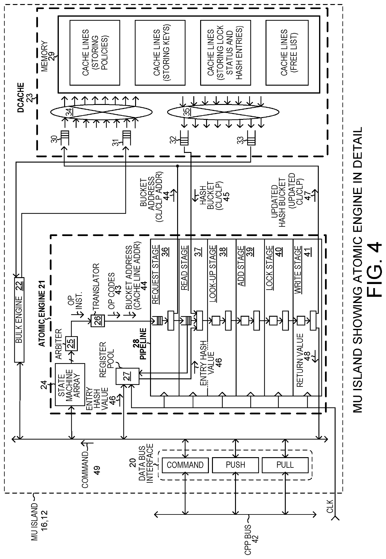
[0011]In one novel aspect, the lock status information for a linked list is stored in the same cache line along with its associated entry hash value. This speeds flow cache operation and reduces the amount of memory accessing required between cache memory and bulk memory. If, on the other hand, the lock information were stored in another cache line, then a lookup attempt may cause two cache line misses as opposed to just one.
[0012]In one example, the lookup engine has an automatic hash entry adding feature. If the lookup engine is charged with doing a lookup operation on a hash value, and it finds no matching entry hash value stored in the CL / CLP, and if there is a vacant lock / hash entry slot in the CL / CLP, then the lookup engine automatically adds the hash value into the entry hash value slot of that vacant lock / hash entry slot. In another novel aspect, it automatically sets the lock status bits of the now-filled slot to indicate an exclusive lock. The requesting thread, upon receiving back the return value, learns that the hash value has been added to the CL / CLP and in response uses the exclusive lock of the linked list to add the key (to be the first entry of the associated linked list of keys). The policy for the flow is similarly added at a memory location associated with the linked list entry into which the key was loaded. In this way, a flow entry (an entry hash value, the key, and the policy) can be added into the flow cache quickly and efficiently. After the flow entry has been added, the thread can release the exclusive lock by writing to the CL / CLP and changing the value of the exclusive lock value for the lock / hash entry.
[0013]As compared to an approach in which the key is stored in the cache line and is obtained directly from a CAM lookup of a second hash value, the flow cache is more memory efficient. As compared to an approach in which every entry hash value has an associated head pointer to the associated linked list of keys, the flow cache is faster. In one novel aspect, there are four lock / hash entry slots in each CL / CLP. The linked list of pointers associated with the first lock / hash entry slot, however, is different from the others in that the memory location where the head of the linked list is found is obtained directly from the address of the CL / CLP. To find the head of this linked list, there is no need for the processor to read a head pointer. This consumes a bit of memory space because the associated memory location for the first lock / hash entry of each cache line has to be allocated even it may not actually be used (may not be filled), but the first lock / hash entry slot is more likely to be filled and contain a matching entry that the other lock / hash entry slots of the CL / CLP. Therefore, the speed improvement due to not having to read head pointers for these first lock / entry slots is worth the nominal amount of memory space that might not be efficiently used. Each of the lock / hash entry slots two, three and four is provided with a head pointer, where these head pointers are stored in the same cache line along with the lock / hash entries. For these lock / hash entry slots two through four where matches are less likely, the more efficient use of memory resources at the expense of speed is elected. Overall the combination of an implicit head pointer for the first lock / entry slot and explicit head pointers for the other lock / hash entry slots tends to result in a superior memory usage and speed tradeoff.
[0014]Advantageously, there is a statistic value slot, a timestamp value slot, and a timeout value slot for the head of the linked list for each of the four lock / hash entry slots of the CL / CLP. The statistics associated with the head entries can be updated without accessing another cache line. This serves to reduce the number of cache lines that are dirtied, and thereby reduces the amount of accessing required between cache memory and external bulk memory.

Problems solved by technology

If, on the other hand, the lock information were stored in another cache line, then a lookup attempt may cause two cache line misses as opposed to just one.
Therefore, the speed improvement due to not having to read head pointers for these first lock / entry slots is worth the nominal amount of memory space that might not be efficiently used.
There are secure software hash algorithms that generate sixty-four bits of entropy, but they are expensive in terms of processing.

Method used


Image

  • High-speed and memory-efficient flow cache for network flow processors
  • High-speed and memory-efficient flow cache for network flow processors
  • High-speed and memory-efficient flow cache for network flow processors

Examples


Embodiment Construction

[0035]Reference will now be made in detail to some embodiments of the invention, examples of which are illustrated in the accompanying drawings.

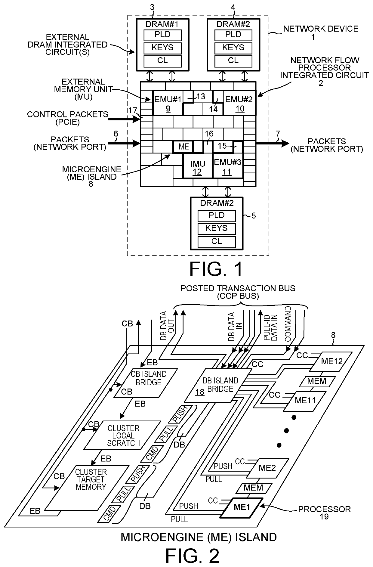
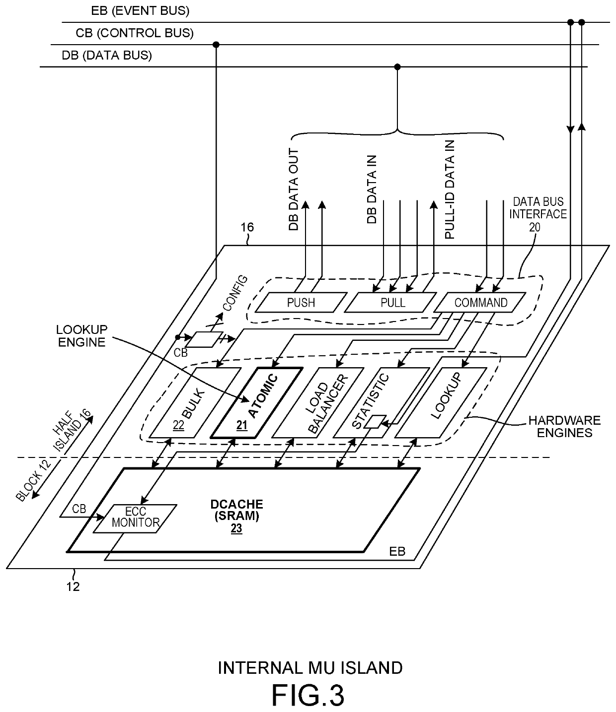
[0036]FIG. 1 is a block diagram of a network device and system 1. The device 1 includes an Island-Based Network Flow Processor (IB-NFP) integrated circuit 2, and three external Dynamic Random Access Memory (DRAM) integrated circuits 3-5. The IB-NFP integrated circuit 2 includes a peripheral first area of input / output circuit blocks. Some of the input / output circuit blocks are for communicating network packets, such as IPv4 packets or IPv6 packets, into and out of the IB-NFP integrated circuit. Others of the input / output blocks are for interfacing the IB-NFP integrated circuit to the external DRAM integrated circuits 3-5. Others of the input / output blocks are for interfacing the IB-NFP to a host computer via a PCIe bus or buses. In the illustration, IPv4 network packets 6 are received onto the overall device and onto the IB-NFP via one of a p...


PUM


Abstract

The flow cache of a network flow processor (NFP) stores flow lookup information in cache lines. Some cache lines are stored in external bulk memory and others are cached in cache memory on the NFP. A cache line includes several lock / hash entry slots. Each slot can store a CAM entry hash value, associated exclusive lock status, and associated shared lock status. The head of a linked list of keys associated with the first slot is implicitly pointed to. For the other lock / entry slots, the cache line stores a head pointer that explicitly points to the head. Due to this architecture, multiple threads can simultaneously process packets of the same flow, obtain lookup information, and update statistics in a fast and memory-efficient manner. Flow entries can be added and deleted while the flow cache is handling packets without the recording of erroneous statistics and timestamp information.

Description

CROSS REFERENCE TO RELATED APPLICATIONS[0001]This application is a continuation of, and claims priority under 35 U.S.C. § 120 from, nonprovisional U.S. patent application Ser. No. 15 / 356,562 entitled “High-Speed And Memory-Efficient Flow Cache For Network Flow Processors,” filed on Nov. 19, 2016, which in turn claims priority under 35 U.S.C. § 119 from U.S. Provisional Application Ser. No. 62 / 257,719, entitled “Improved Hash And Lock Caching Scheme,” filed on Nov. 19, 2015. The subject matter of both identified applications is incorporated herein by reference.TECHNICAL FIELD[0002]The described embodiments relate generally to flow caches for network flow processors.REFERENCE TO ASCII TEXT FILE APPENDIX[0003]This application includes an ASCII text file appendix containing source code that embodies the inventions described herein. A portion of the disclosure of this patent document contains material that is subject to copyright protection. All the material in the ASCII text file append...

Claims


Application Information

Patent Timeline
Patent Type & Authority Patents(United States)
IPC IPC(8): G06F12/00G06F12/14H04L9/06G06F12/0802
CPCH04L9/0643G06F12/1408G06F12/0802H04L9/3239H04L2209/125H04L9/3297G06F12/0875H04L9/50
Inventor PEER, EDWIN S.
Owner NETRONOME SYST
Learn More