
Sources of optical radiation and methods for providing low-speckle optical radiation, and systems and methods using them

a source of optical radiation and source of low-speckle optical radiation, applied in the field of optical imaging systems, can solve the problems of preventing full-field imaging applications, introducing undesirable spatial coherence, and traditional low-spatial coherence sources such as thermal sources and leds, and achieving low spatial coherence, low temporal coherence, and high power per mode

Active Publication Date: 2020-06-09
YALE UNIV +1
View PDF19 Cites 2 Cited by
  • Summary
  • Abstract
  • Description
  • Claims
  • Application Information

AI Technical Summary

Benefits of technology

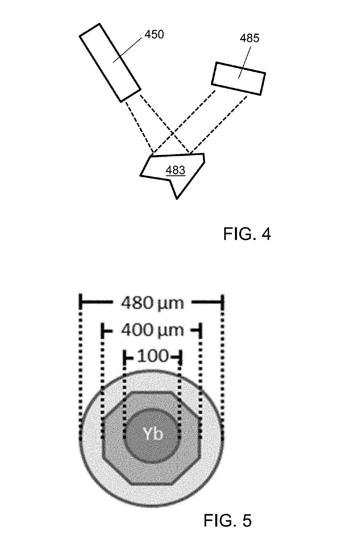
[0007]In certain aspects, the present disclosure relates to a fiber-based amplified spontaneous emission (ASE) source with low spatial coherence, low temporal coherence, and high power per mode. ASE can be produced by optically pumping a large gain core multimode fiber, for example while minimizing optical feedback to avoid lasing. In one particular embodiment, the fiber ASE source can provide 270 mW of continuous wave emission, centered at λ=1055 nm with a full-width half-maximum bandwidth of 74 nm. The emission can be distributed among as many as ˜70 spatial modes, enabling efficient speckle suppression when combined with spectral compounding. The present disclosure also relates to the use of the fiber ASE source to provide speckle-free full field imaging. Accordingly, the fiber ASE sources described herein can provide a unique combination of high power per mode with both low spatial and low temporal coherence, making them attractive sources full-field imaging and ranging applications.

Problems solved by technology

However, the high spatial coherence of existing ASE sources has precluded their use in full-field imaging applications, where spatial coherence introduces undesirable artifacts such as speckle.
By comparison, traditional low spatial coherence sources such as thermal sources and LEDs do not provide the required power per mode for high speed, full-field imaging applications.
However, an optical fiber based light source with low spatial coherence has not been demonstrated.

Method used


Image

  • Sources of optical radiation and methods for providing low-speckle optical radiation, and systems and methods using them
  • Sources of optical radiation and methods for providing low-speckle optical radiation, and systems and methods using them
  • Sources of optical radiation and methods for providing low-speckle optical radiation, and systems and methods using them

Examples


Embodiment Construction

[0047]Example active optical fibers, systems and methods are described herein. Any example embodiment or feature described herein is not necessarily to be construed as preferred or advantageous over other embodiments or features. The example embodiments and features described herein are not meant to be limiting. It will be readily understood that certain aspects of the disclosed systems and methods can be arranged and combined in a wide variety of different configurations, all of which are contemplated herein.

[0048]Furthermore, the particular arrangements shown in the figures should not be viewed as limiting. It should be understood that other embodiments might include more or less of each element shown in a given figure. In addition, some of the illustrated elements may be combined or omitted. Similarly, an example embodiment may include elements that are not illustrated in the figures.

[0049]In the following discussion it is assumed that the reader has the basic knowledge of the st...


PUM

PropertyMeasurementUnit
diameteraaaaaaaaaa
diameteraaaaaaaaaa
thicknessaaaaaaaaaa

Abstract

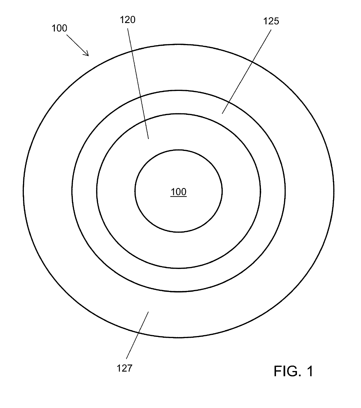
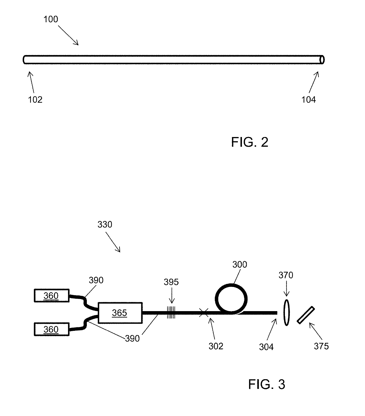
The present disclosure relates more particularly to active optical fibers, amplified spontaneous emission (ASE) sources using such active optical fibers, and imaging and detection systems and methods using such ASE sources. In one aspect, the disclosure provides an active optical fiber that includes a rare earth-doped gain core configured to emit radiation at at least a peak wavelength emitted wavelength when pumped with pump radiation having a pump wavelength; a pump core surrounding the gain core; and a cladding surrounding the pump core, wherein the value M=16R2(NA)2 / λ2 in which R is the gain core radius, NA is the active optical fiber numerical aperture, and λ is the peak emitted wavelength, is at least 50, or at least 100. The present disclosure also provides an optical source that includes the optical fiber coupled to a pump source.

Description

CROSS-REFERENCE TO RELATED APPLICATIONS[0001]This application claims the benefit of priority of U.S. Provisional Patent Application No. 62 / 167,729, which is hereby incorporated herein by reference in its entirety.STATEMENT OF GOVERNMENT SUPPORT[0002]This invention was made with government support under Grants Nos. 1R21EB016163-01A1 and 1R21HL125125-01A1 awarded by the National Institutes of Health (NIH). The government has certain rights in the invention.BACKGROUND OF THE DISCLOSURE[0003]1. Field of the Disclosure[0004]The present disclosure relates generally to optical imaging systems. The present disclosure relates more particularly to active optical fibers, amplified spontaneous emission (ASE) sources using such active optical fibers, and imaging and detection systems and methods using such ASE sources.[0005]2. Technical Background[0006]Conventional amplified spontaneous emission (ASE) based light sources combine broadband emission, similar to a light emitting diode (LED), with h...

Claims


Application Information

Patent Timeline
Patent Type & Authority Patents(United States)
IPC IPC(8): H01S3/16G01J3/02G02B6/02G01S17/00G01S7/481G01S7/4911G01J3/10G01J3/18H01S3/067H01S3/00G02B27/48G01B11/14H01S3/094
CPCH01S3/1618G01J3/10G01J3/1895H01S3/1603H01S3/06729H01S3/0078G01S17/00G01S7/4911G01J3/0218G01S7/4818G01J3/108H01S3/094007G01B11/14H01S2301/02
Inventor REDDING, BRANDONAHMADI, PEYMANSEIFERT, MARTINCAO, HUI
Owner YALE UNIV
Learn More