Polarizing plate and optical apparatus provided with the same
a technology of polarizing plates and optical apparatuses, applied in the direction of instruments, polarising elements, optical light guides, etc., can solve the problems of difficult to obtain high durability while maintaining high transmittance characteristics, and achieve high durability and transmittance characteristics. high
- Summary
- Abstract
- Description
- Claims
- Application Information
AI Technical Summary
Benefits of technology
Problems solved by technology
Method used
Image

Examples
modification example
[0083]It should be noted that the present invention is not limited to the above-mentioned embodiments, and variations and improvements within a range that can achieve the object of the present invention are included in the present invention. For example, the application of the polarizing plate of the present embodiment is not limited to a liquid crystal projector, and can be used for various applications.
[0084]Here, FIG. 3 is a schematic cross-sectional view illustrating a polarizing plate 2 according to a modification example of the above embodiment. The polarizing plate 2 according to the modification example has the same configuration as that of the polarizing plate 1 except that the configuration of the protection layer 25 is different from that of the polarizing plate 1 illustrated in FIG. 1 described above. In FIG. 3, the same components as those of the polarizing plate 1 illustrated in FIG. 1 are denoted by the same reference numerals, and descriptions thereof are omitted bel...
example 1 and example 2
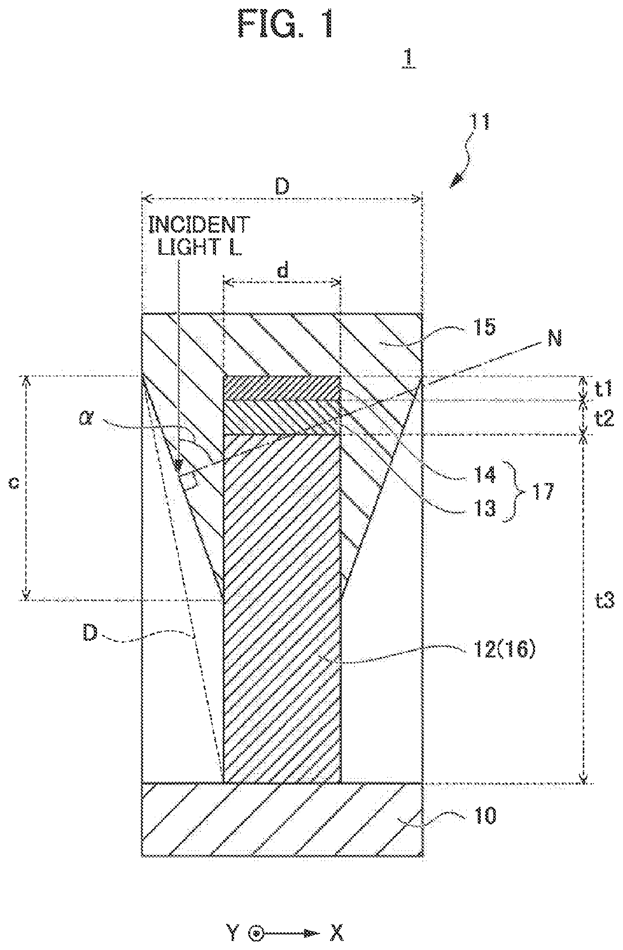
[0090]In Example 1 and Example 2, each polarizing plate 1 having the structure illustrated in FIG. 1 and having the parameters shown in Table 1 below was subjected to simulation. More specifically, the optical characteristics of these polarizing plates were verified by electromagnetic field simulation according to the Rigorous Coupled Wave Analysis (RCWA) method. For the simulation, grating simulator Gsolver available from Grating Solver Development Company was used. In addition, aluminum was used as the reflection layer, silica was used as the dielectric layer, silicon was used as the absorption layer, and silica was used as the protection layer.
[0091]
TABLE 1Example 1Example 2Pitch of grid-shaped projecting portion (nm)150150Line width (nm)37.537.5Reflection layer film thickness (nm)165165Dielectric layer film thickness (nm)1517Absorption layer film thickness (nm)1014Protection layer film thickness (nm)1024Protection layer maximum width (nm)5190
[0092]For each of the polarizing plat...
example 3
[0098]In Example 3, each polarizing plate 2 having the structure shown in FIG. 3 and having the parameters shown in Table 2 below was subjected to simulation. The simulation was performed under the same conditions as those in Examples 1 and 2. The P-polarized light transmittance of each wavelength obtained as a result of the simulation is shown in Table 3.
[0099]
TABLE 2Example 3Pitch of grid-shaped projecting portion (nm)150Line width (nm)37.5Reflection layer film thickness (nm)165Dielectric layer film thickness (nm)17Absorption layer film thickness (nm)14Protection layer film thickness (nm)24Protection layer maximum width (nm)90Side surface coverage (%)15.8Protection layer width of reflection layer lower portion (nm)10
[0100]
TABLE 3WavelengthTransmittance (%)R (650 nm)93.54G (550 nm)92.38B (450 nm)91.06
[0101]From the results shown in Table 3, it was confirmed that, even the polarizing plate according to the modification example of the above embodiment still can obtain P-polarized lig...
PUM
| Property | Measurement | Unit |
|---|---|---|
| thickness | aaaaa | aaaaa |
| wavelength | aaaaa | aaaaa |
| thickness | aaaaa | aaaaa |
Abstract
Description
Claims
Application Information
 - R&D
- Intellectual Property
- Life Sciences
- Materials
- Tech Scout
- Unparalleled Data Quality
- Higher Quality Content
- 60% Fewer Hallucinations
Browse by: Latest US Patents, China's latest patents, Technical Efficacy Thesaurus, Application Domain, Technology Topic, Popular Technical Reports.
© 2025 PatSnap. All rights reserved.Legal|Privacy policy|Modern Slavery Act Transparency Statement|Sitemap|About US| Contact US: help@patsnap.com