Balloon play apparatus or the like

a technology of balloons and play parts, applied in the field of balloons, can solve the problems of degrading the play value of the apparatus, reducing the volume of the pump chamber, and reducing the appeal of the apparatus, so as to reduce the movement of the squirting handle, the effect of minimizing the stroke length

Active Publication Date: 2020-07-21
PUBLICOVER MARK +1
View PDF25 Cites 5 Cited by
  • Summary
  • Abstract
  • Description
  • Claims
  • Application Information

AI Technical Summary

Benefits of technology

[0006]In another aspect, the tube may travel from the reservoir and then travel in contact with the balloon toward a single direction with a nozzle at its end (not shown in drawings). This is a very simple configuration which will also propel the balloon in various directions in a three dimensional space.
[0028]“Near the body or hand” is defined as the reservoir being either adjacent to a hand that may hold the string; or where a part of the hand is in contact with the reservoir such that the hand is at least partially supporting the weight of the reservoir; or where the reservoir is located in close proximity to the body such that the weight of the reservoir does not impede the buoyancy of the balloon. For example, a person may be holding the reservoir directly where the reservoir is configured to be held by a human hand spanning a size of 3 to 12 inches when the fingers and thumb are open and outstretched to their maximum extension. Or, the reservoir may be strapped or otherwise coupled to the hand so that the user may grasp other items. For example the reservoir could be attached to the back of a user's hand. By holding the reservoir adjacent or in a hand clasp in the various manners described, the balloon buoyancy is less impeded. Close proximity to the body defines a distance within the maximum extension of a person's arm reach regardless of their size. A small child with have a smaller reach than a large adult, but the reservoir is within their respective arm extensions or reach. So, in another example, the reservoir could be attached to a person's body or clothing within their reach distance such that the body at least partially supports the weight of the reservoir with or without fluid. This configuration would also reduce or completely remove almost all of the liquid weight affecting buoyancy of the balloon, except for the smaller amount flowing through and along the tube or tubes to the nozzle located at or near the floating balloon.
[0034]Another pump mechanism may be a syringe-type pump, or a piston-type pump where the user moves a handle to operate a piston and pressurize a reservoir, then activates a triggering mechanism (such as a gun trigger type design or the like for example) to squirt the liquid. A reservoir 600 is attached to a ball 602 via a clevis assembly comprising an upward extending eye projection, such as a lug 604, and a clevis pin 606, which may comprise a machine screw and cap nut. A non-squirting handle 608 extends from the reservoir assembly. Also extending from the reservoir assembly is a squirting handle. The squirting handle is attached to the reservoir assembly and a pump piston by a shaft which passes through an opening defined by a shaft support member. A helical compression spring surrounds the shaft or the like and is between the piston and a wall of the reservoir. A spring is compressed as the user pulls upwardly on the squirting handle. As the pump piston moves upwardly, the volume of the pump chamber is reduced and pressurized air is pushed through a one way valve into a tube and deposited into the reservoir. A tube can then allow ambient air pressure to vent into the lower portion of the pump chamber in order to prevent a vacuum from developing during the movement of the piston. When the user is no longer pulling upwardly, the pump piston is at increased pressure in the reservoir. The diameter of the pump piston 612 is selected so that a minimal stroke length will result in adequate pressurization of the reservoir between 0.4 to 10 psi in a minimal number of strokes. Minimizing the stroke length reduces the movement of the squirting handle relative to the balloon. The spring should be selected so that the force required for the user to move the pump does not exceed the strength of either the child or adult user for which the disclosed apparatus is designed. Alternate arrangements may include a double acting pump mechanism that uses springs to push a piston toward a center position and thus pump pressurized air into the reservoir when the piston is moved either upwardly or downwardly.

Problems solved by technology

Because balloons have weight concerns and limitations, it has not been considered to use injected water from a reservoir up a tube to an elevated and buoyant balloon.
Mixing these two mediums (water and air, for example) lessens the weight but not the play fun of the device.
The upper limit is not based simply on the weight; but the cost of lighter than air gases such as helium can make a play apparatus such as the disclosed device more expensive and thus less appealing to purchase if too much is required for buoyancy.
While larger balloons and larger diameter tubes can be fabricated, the subsequent play value of the apparatus is degraded which reduces the utility of its purpose.
For example, signs, overhead wires and other unforeseen obstacles may impede the floating balloon.
The body weights of the users that fall within these heights are not a sufficient factor which would impede the operation of the disclosed device.

Method used


Image

  • Balloon play apparatus or the like
  • Balloon play apparatus or the like
  • Balloon play apparatus or the like

Examples


Embodiment Construction

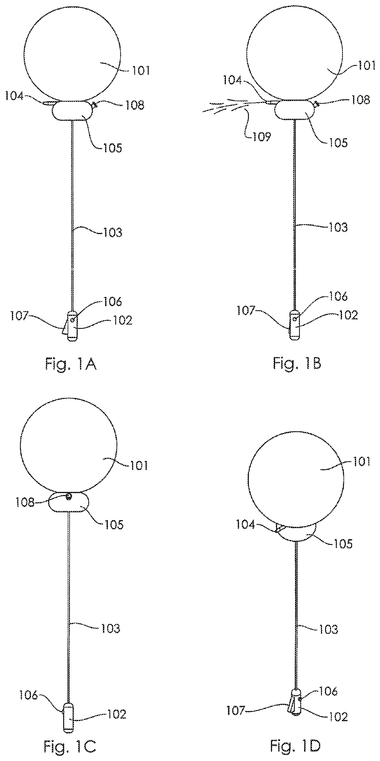
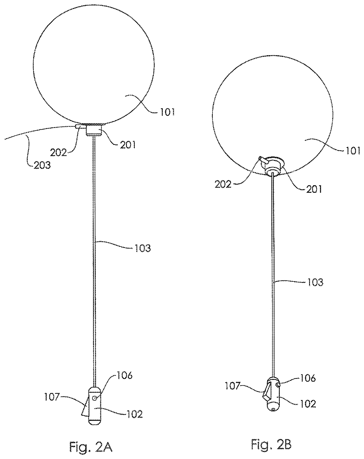
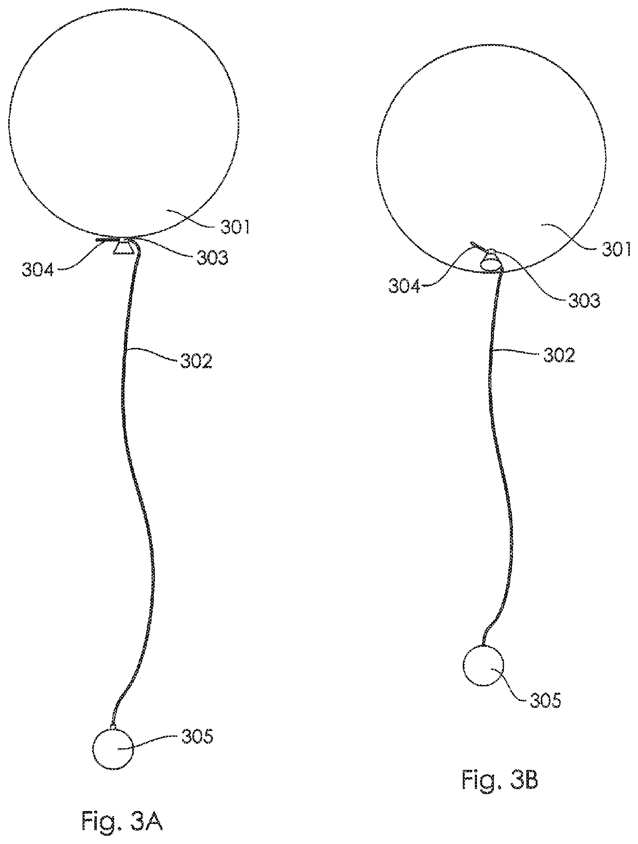
[0072]Referring to FIGS. 1A through 9B, there is illustrated therein a new and improved method of balloon water play previously summarized.

[0073]While the apparatus has been described in connection with a preferred embodiment or embodiments, it is not intended to limit the scope of the apparatus to the particular form set forth, but on the contrary, it is intended to cover such alternatives, modifications, and equivalents as may be within the spirit and scope of the apparatus as defined by the listed claims.

[0074]FIG. 1A is a rod-supported squirting balloon comprising of an inflated balloon, 101, a handle, 102, a connector that is a rod, 103. A mechanism is provided to cause liquid to be expelled from the apparatus. The mechanism includes a nozzle, 104, having an orifice, a water reservoir, 105, that defines a reservoir chamber that contains a body of water, a trigger button, 106, a pump lever, 107, and a reservoir fill inlet, 108. The orifice is in fluid communication with the rese...


PUM


Abstract

A play apparatus has a gas filled balloon and an opening through which fluid is squirted or otherwise released. Fluid is delivered to the opening from an adjacent or nearby reservoir which is connected to at least one hollow tube whereby liquid is transferred from the reservoir to the release point on or adjacent to the balloon, such that the buoyancy of the balloon is unimpeded, for the purposes of play and amusement.

Description

CROSS REFERENCE TO RELATED APPLICATIONS[0001]This claims the benefit of U.S. Provisional Applications Nos. 62 / 100,170 and 62 / 262,367, which are incorporated herein by reference in their entireties.BACKGROUND AND SUMMARY[0002]This disclosure relates to a balloon having an opening which squirts or otherwise releases contained water (or other fluid) from an adjacent or nearby reservoir which is connected to at least one hollow tube or conduit, or rod whereby liquid is transferred from the reservoir to the release point on the balloon for the purposes of play and amusement. Water is the fluid described herein, but any fluid or liquid may be utilized in lieu of water.[0003]The “squirting balloon” apparatus releases or otherwise emits water from the balloon itself or from a location adjacent or nearby the balloon. The water is expelled through an aperture located on an external surface of the apparatus, such as via the orifice of a nozzle, which is located above the level of the ground.[0...

Claims


Application Information

Patent Timeline
Patent Type & Authority Patents(United States)
IPC IPC(8): A63H27/10A63H37/00B05B9/04B05B9/08
CPCB05B9/0805A63H37/00B05B9/0403A63H27/10A63H2027/1041A63H2027/1075A63H2027/1083A63H2027/1008
Inventor PUBLICOVER, MARKPUBLICOVER, JACOB
Owner PUBLICOVER MARK
Why Eureka
Try Eureka