
Monitoring and control implement for crop improvement

a technology of monitoring and control implements, applied in the direction of instruments, television systems, image enhancement, etc., can solve the problems of managing large farms and fields and crop yield improvement, and achieve the effects of improving crop yield, saving water, and preserving land

Active Publication Date: 2020-07-28
DOLLY Y WU PLLC
View PDF55 Cites 17 Cited by
  • Summary
  • Abstract
  • Description
  • Claims
  • Application Information

AI Technical Summary

Benefits of technology

The patent describes a portable system with cameras, sensors, and a computer program that can detect problems with crops and provide valuable information to farmers to improve yield. The system can also feed and monitor crops, and control them to improve growth. This technology helps to increase crop yield, protect the soil, save water, and reduce the use of harmful chemicals in each crop field.

Problems solved by technology

The terrain may be uneven; there may be obstacles or soggy ground; there may be too much residue; the noxious spray drifts; there are weeds, fungus, insects, water shortage, and other problems.
There have also been problems related to managing large farms and fields and crop yield improvement.

Method used


Image

  • Monitoring and control implement for crop improvement
  • Monitoring and control implement for crop improvement
  • Monitoring and control implement for crop improvement

Examples


example spray boom

Control

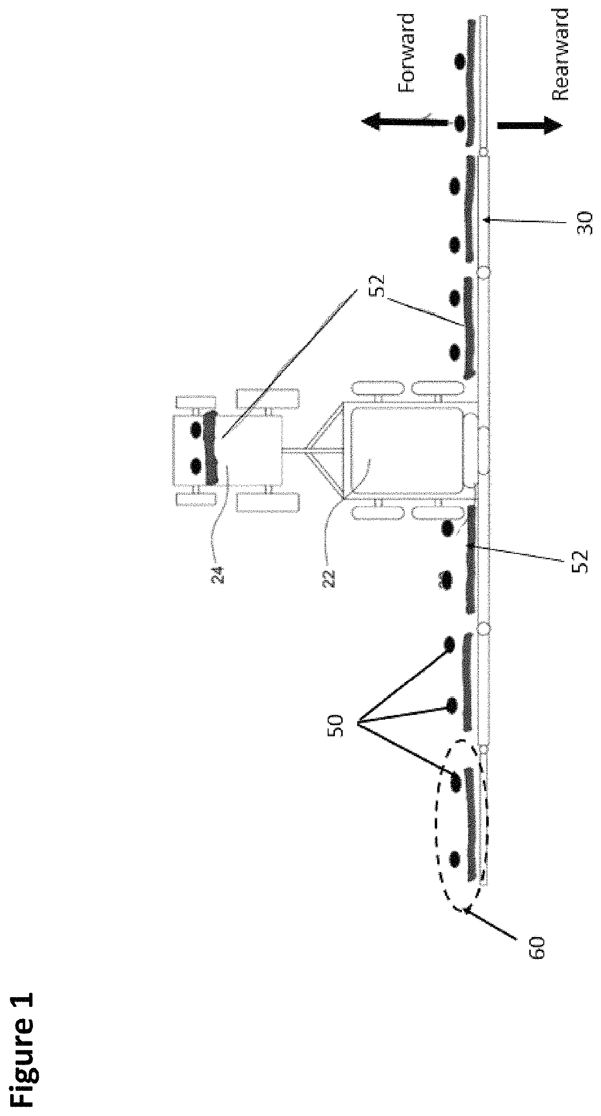
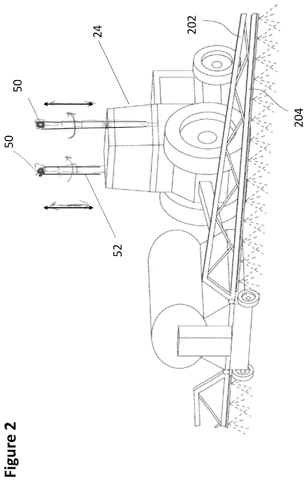
[0126]Some spray booms have proximity sensors mounted on the underside of boom sections in order to check the distance between the boom and the ground or between the boom and the crop leaf. The spray boom sections then respond by moving up and down, for example, to maintain a fixed height above the plant leaves or ground height. For articulated booms, the boom sections bend and fold so that the height of each section of the boom follows or tracks the level of the terrain or crop height. By including information from the image sensor or videos, the vehicle or booms are able to look ahead: to anticipate changes in the terrain, hills, ditches, obstacles, and so on. Also by looking forward past the immediate location of the boom, the image sensors in some embodiments, provide information to the CPU to first assess the average height, average color, average mass and other characteristics of the crop. Deviations from the average values are used by the processors to detect anomalous...

example implementations

Alternative Example Implementations

[0163]Another embodiment includes the use of re-purposed smartphones electronics where the processor circuits have been re-programmed so that the smartphones perform the different functions in real time. This disclosure is not limited to smartphones (e.g. smart notepads, smart watches). Rather, any electronics instruments having many of features such as on smartphones (e.g. in 2017) can be re-purposed for agricultural monitoring, control and analysis use. The “smartphones” electronics mounted on attachment fixtures may not have the touch screen, but much of the rest of the electronics still remain. For example, smartphones have fast and slower speed communications channels. The LTE, Bluetooth, 5G and WIFI speed processing are suitable and compatible with speeds for weed identification. The voiceband frequencies on smartphones are comparable with fast CAN-bus. Smartphone electronics include two or three processing circuits: DSP, a CPU logic micropro...


PUM


Abstract

An example machinery includes an automated crop management motorized vehicle having an intelligent, modularized image sensor (e.g. camera or video) system that is portable to other crop management vehicles such as a combine, planter or a tillage machine. The image sensor system includes a framework having a bank of procedures for monitoring and control of navigation, spray application, weeding, seeding, machine configuration, in real time as the machines go through a crop field throughout a crop cycle. One example implementation includes electronic circuits, with more than one set mounted on a platform that facilitates moving the setup to other agricultural machines. The framework captures, preserves and corrects the captured images for real time analysis and response, and for spray management to improve crop yield that is correlated with the machine settings and crop management practices.

Description

PRIOR APPLICATIONS[0001]This application is a continuation-in-part of U.S. patent application Ser. No. 15 / 424,809, titled Image Sensor and Module Useful for Agricultural Crops and filed on Feb. 4, 2017, which claims the benefit of U.S. Provisional Application No. 62 / 443,784, titled Monitoring and Control System for Crop Management and filed on Jan. 8, 2017.FIELD OF THE DISCLOSURE[0002]Equipment and system for improving, monitoring, managing, and determining the yield of agricultural fields by using sensing devices and controlling agricultural vehicles throughout a crop cycle.BACKGROUND OF THE DISCLOSURE[0003]An agricultural cycle relates to the cyclic activities from the growth of to the harvest of crops such as wheat, corn, soybeans, rice, vegetables, and fruits. The activities include preparing the soil, removing weeds and plant residue and rocks, seeding, irrigating, fertilizing, moving plants when they grow bigger, killing bugs and fungus, wind-rowing, harvesting, baling, combin...

Claims


Application Information

Patent Timeline
Patent Type & Authority Patents(United States)
IPC IPC(8): A01C21/00H04N5/225H04N7/18B60R11/04
CPCB60R11/04H04N7/181H04N5/2252H04N7/188A01C21/007A01C21/005G06T7/0004G06T7/73G06T2207/10021G06T2207/10028G06T2207/30188A01M7/0089H04N23/51
Inventor WU, DOLLY Y.DEUTSCH, TIMOTHY A.
Owner DOLLY Y WU PLLC
Learn More