Preparation method for composite porous structure and composite porous structure made thereby

a composite porous structure and composite porous technology, applied in membrane technology, membranes, coatings, etc., can solve the problems of environmental pollution, not meeting current environmental protection demands, long preparation time and increased cost, etc., and achieves simple and economic methods. , the effect of more potential for commercial practi

Active Publication Date: 2020-08-11
EXTREMEM INC
View PDF4 Cites 0 Cited by
  • Summary
  • Abstract
  • Description
  • Claims
  • Application Information

AI Technical Summary

Benefits of technology

[0008]In view of the technical defects of the conventional porous thin film or its preparation method, an objective of the present invention is to provide a simple and economic method for preparing a composite porous structure, and thus has more potential for commercial practice.
[0009]Another objective of the present invention is to provide a method for preparing a composite porous structure, which can produce a composite porous structure with a blocking efficiency more than 99%.
[0011]According to the present invention, since a cooling fluid is continuously fed in the system, the cooling fluid contacts the first surface of the porous substrate, and thus a part of the cooling fluid would be at least filled in the pores of the porous substrate, and even a portion of the cooling fluid flows to the second surface through the pores of the porous substrate. When the multiple molten particles hit on the second surface of the porous substrate, the thermal energy accompanied with the molten particles can continuously vaporize the cooling fluid in the pores into the steam, and such steam will pass through the coating layer formed by the molten particles and create many micropores. Since the molten particles hit the second surface while the cooling fluid continuously contacts the first surface, the cooling fluid can remove the excessive heat energy, maintain the overall temperature of the porous substrate and continuously fill the pores in the porous substrate. Therefore, the failure that the liquid in the pores cannot be vaporized and fails to form micropores when the thermal spraying method is adopted alone and the porous substrate is gradually heated can be overcome. Therefore, the preparation method of the present invention has a simple manufacturing process, greatly shortens the preparation time, and obtains a composite porous structure with high uniformity in pore size, and thus can make the composite porous structure have a blocking efficiency more than 99%.
[0012]According to the present invention, the molten particles include substantially fully-molten particles or semi-molten particles, and therefore the melted particles may be liquid or solid. The temperature difference between the molten particles and the porous substrate can affect the final morphology of the molten particles stacked on the second surface of the porous substrate, as well as the pore size of the coating layer. Preferably, the temperature of the molten particles is higher than the temperature of the cooling fluid; in this way, the cooling fluid can have a better cooling effect on the porous substrate.
[0018]Preferably, step (a) can include step (a1): preparing a porous substrate having the pores; and step (a2): filling a liquid into the pores. This technical means can make the pores filled with sufficient liquid, and thereby providing a method for preparing a composite porous structure with a higher pore diameter consistency.
[0030]In some embodiments, the material of the porous substrate can be an organic polymer material, a ceramic material, or a metal material. Based on the aforementioned preparation method, inorganic coating organic substrate composite porous structure, organic coating organic substrate composite porous structure, inorganic coating ceramic substrate composite porous structure, organic coating ceramic substrate composite porous structure, inorganic coating metal substrate composite porous structure, organic coating metal substrate composite porous structure, etc. can be obtained. For example, the material of the porous substrate is an organic polymer material, which can include, but is not limited to polyolefins such as polyethylene, polypropylene, etc., polytetrafluoroethylene, polyacrylonitrile, polyurethane, etc.; the material of the porous substrate is a ceramic material, which can include, but is not limited to, alumina, silica, magnesia, titania, zinc oxide, zirconium oxide, or a combination thereof; the material of the porous substrate is a metal material, which can include, but is not limited to, cobalt, iron, nickel, copper, aluminum or a combination thereof. Compared with the existing porous films, the composite porous structure of the present invention can select more combinations of materials, thereby increasing the application potential.

Problems solved by technology

All of them require complicated preparation steps, which results in a lengthy preparation time and an increased cost.
Furthermore, the aforementioned methods frequently use harmful solvents or organometallic compounds during the preparation of precursor materials, which also results in environmental pollution and does not meet current environmental protection demands.
Although thermal spraying technique can simplify or shorten the film production process, the porous film obtained by the conventional thermal spraying has non-uniformity and wide distribution in pore size, resulting in a poor blocking efficiency.

Method used


Image

  • Preparation method for composite porous structure and composite porous structure made thereby
  • Preparation method for composite porous structure and composite porous structure made thereby
  • Preparation method for composite porous structure and composite porous structure made thereby

Examples


example 1

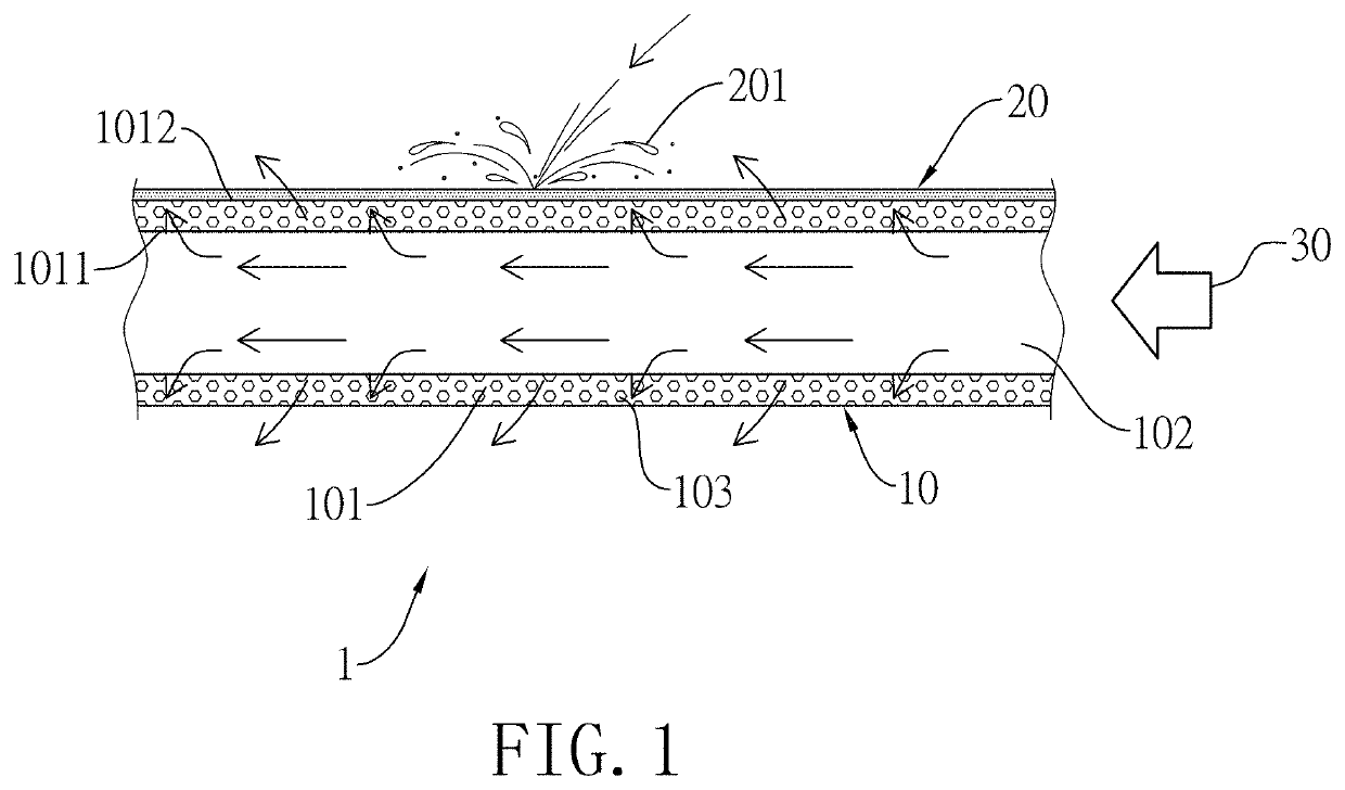
[0041]First, referring now to FIG. 1, a hollow tubular porous substrate 10 in the step (a1) is prepared. The porous substrate 10 has a tube wall 101, an axial channel 102 and multiple pores 103. The axial channel 102 is formed in the tube wall 101, and the pores 103 are concavely formed on the tube wall 101. The tube wall 101 has a first surface 1011 (i.e., an inner wall surface) and a second surface 1012 (i.e., an outer wall surface) opposite to the first surface 1011. The tube wall 101 has a thickness of 2.5 mm, a length of 300 mm, an inner diameter of 29.5 mm and an outer diameter of 30 mm. The porous substrate 10 is made of stainless steel and has an average diameter of 3 μm. Subsequently, in the step (a2), the porous substrate 10 is immersed in a tank filled with deionized water to allow the multiple pores 103 in the porous substrate 10 to be full with deionized water.

[0042]Next, referring to FIG. 1, the cooling fluid 30 at 25° C. is fed into the axial channel 102 at a flow rat...

example 2

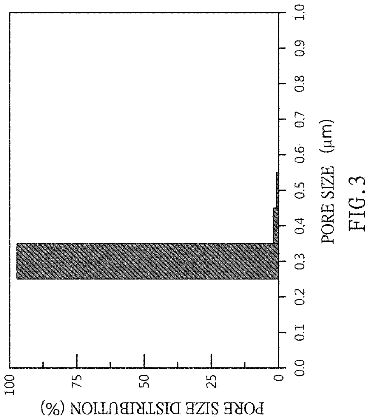
[0045]The preparation method of Example 2 is similar to the preparation method of Example 1, the difference lies in that Example 2 repeats step (b) 5 times. The composite porous structure prepared in accordance with the preparation method of Example 2 comprises a porous substrate and a coating layer having multiple micropores formed on the second surface of the porous substrate. The average thickness of the coating layer is 48 μm and the average pore diameter of the micropores in the coating layer is about 0.32 μm. The pore size distribution thereof is shown in FIG. 3, wherein the micropores having pore diameters larger than 0.35 μm take up only 2.7% of the total micropores. In addition, the composite porous structure in accordance with the example has a blocking efficiency of 99% for the 0.2 μm polystyrene standard particles.


PUM

PropertyMeasurementUnit
flow rateaaaaaaaaaa
flow rateaaaaaaaaaa
thicknessaaaaaaaaaa

Abstract

The present invention provides a preparation method for a composite porous structure, comprising the following steps: step (a): preparing a porous substrate having multiple pores, a first surface and a second surface; and step (b): continuously feeding a cooling fluid to contact the first surface and to flow continuously to the second surface through the pores of the porous substrate, and heating a coating material to multiple molten particles by a heat source and spraying the molten particles onto the second surface of the porous substrate, so as to form a coating layer having multiple micropores on the second surface of the porous substrate and obtain the composite porous structure formed. Besides, also provided is a composite porous structure prepared by the preparation method.

Description

BACKGROUND OF THE INVENTION1. Field of the Invention[0001]The present invention relates to a composite porous structure and a method for preparing the same, and more particularly to a composite porous structure for film separation and a method for preparing the same.2. Description of the Prior Arts[0002]Thin film separation technology utilizes the difference in the materials passing through the thin film in the presence of a driving force, so as to achieve separation, concentration or purification. It has the advantages of high selectivity, easy operation, energy saving, easy amplification and so on, so it has been widely used in various industries in recent years, especially the industries of precision chemical, food, pollution prevention, biomedical engineering, biotechnology and so on, whose demands for thin film separation technology have grown rapidly.[0003]According to the particle sizes that the porous thin films can block, the thin film separation technology can be classifie...

Claims


Application Information

Patent Timeline
Patent Type & Authority Patents(United States)
IPC IPC(8): B01D61/14C23C4/134B01D69/02B01D69/12B01D71/02C23C4/02B01D67/00B01D69/04C23C4/11
CPCB01D69/12C23C4/134B01D61/147B01D71/025C23C4/11B01D69/02B01D69/04C23C4/02B01D67/0074B01D67/0079B01D2323/08B01D2325/02B01D2325/04B01D63/065B01D67/002B01D67/0023B01D67/0053B01D67/0069B01D71/26B01D71/36B01D2323/26C23C4/10C23C4/18C23C4/129C23C4/131B01D2323/082B01D2325/02831B01D67/00044B01D67/00414B01D67/0093C08J9/40
Inventor LI, YU-LINGKANG, CHAO-HSIANG
Owner EXTREMEM INC
Why Eureka
Try Eureka