
Implant and method for manufacturing same

a manufacturing method and implant technology, applied in the field of implants and manufacturing methods, can solve the problems of vascular occlusion, gradual overgrowth of stents, and loss of light, and achieve the effects of promoting a prolonged anti-inflammatory effect of implants, reducing interaction, and simple and economical methods

Active Publication Date: 2011-01-13
BIOTRONIK AG
View PDF8 Cites 3 Cited by
  • Summary
  • Abstract
  • Description
  • Claims
  • Application Information

AI Technical Summary

Benefits of technology

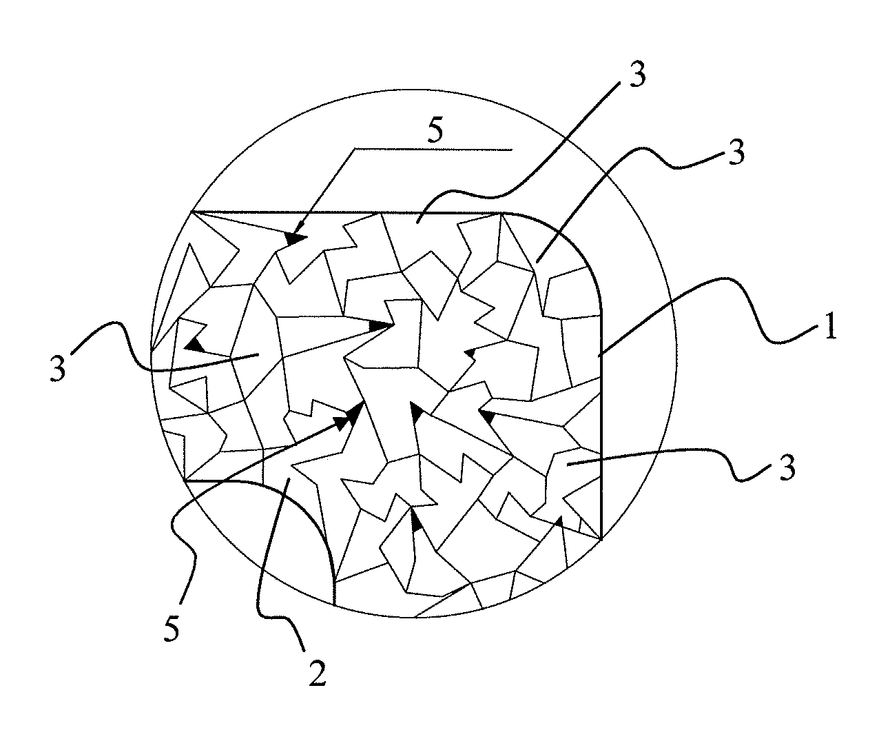
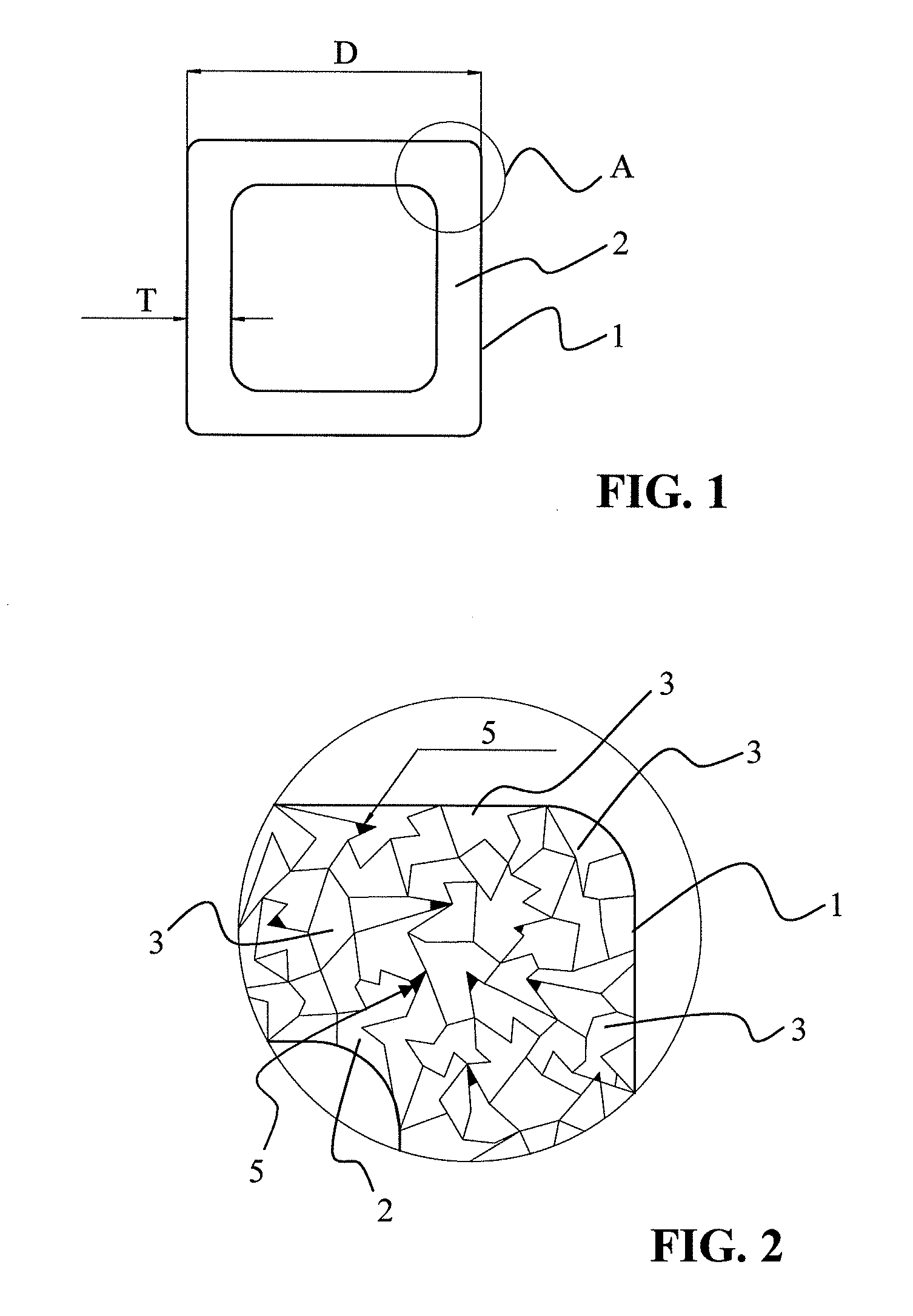
[0011]A feature of the present invention, therefore, is to provide a simple and economical method for manufacturing an implant, preferably made of a metallic material, which promotes a prolonged anti-inflammatory effect of the implant after introduction into the organism being treated. It is an aim that no solid or liquid materials are released. A further aim is to minimize interaction with the material of the implant body or the reaction products thereof. Accordingly, a further object of the invention is to provide such an implant.

Problems solved by technology

Use of stents allows constricted regions in the blood vessels to be expanded, resulting in lumen gain.
Although the optimal vessel cross section primarily necessary for successful treatment may be achieved by the use of stents or other implants, the permanent presence of such a foreign body initiates a cascade of microbiological processes which may promote inflammation of the treated blood vessel or a necrotic alteration of the vessel, for example, and which may lead to gradual overgrowth of the stent as the result of plaque formation.
In the worst case this alteration of the blood vessel may result in vascular occlusion.
As a result of this process the implant loses its mechanical integrity at a specific time.
However, such a plasma treatment of implants requires complicated equipment and involves a high level of manual effort.
Filigreed components such as stents require intricate fine motor skills for the charging procedures which currently are not achievable using automatic handling systems.
Furthermore, such plasma treatments result in loading with materials having anti-inflammatory activity only directly at the surface, i.e., to a depth of a few nm.

Method used


Image

  • Implant and method for manufacturing same
  • Implant and method for manufacturing same

Examples


example 1

[0048]A stent having a body composed of an iron-based alloy containing at least 98% by weight iron, for example the alloys C10, C15, or C20, is subjected to reducing heat treatment at a temperature of approximately 850° C. in a carrier gas containing carbon (for example, a mixture of 60% by volume methanol and 40% by volume nitrogen) for approximately 1.5 hours. During this process, generally referred to as gas carburization, gaseous carbon monoxide dissociates into atomic carbon and oxygen at the surface of the part being treated. The carbon atoms are absorbed by the metal and subsequently diffuse into the stent surface. The depth of diffusion and the carbon gradient in the matrix of the iron alloy may be varied, depending on the duration of treatment. The parameters of gas mixture, time, temperature, and concentration of the carbon-containing gas in particular may be varied (as an additional inert gas, argon is able to reduce the available carbon, and thus, the carbon diffusion). ...

example 2

[0054]Analogous to Example 1, with the following composition of the material of the stent (iron-based alloy containing Mn as stent material): Fe alloy containing 82% by weight Fe, 15% by weight Mn, and 3% by weight Pd (Fe82Mn15Pd3). Hydrogen sulfide is used as carrier gas for cavity production.

example 3

[0055]For all stents manufactured according to Examples 1 and 2, as the final step a coating of parylene C, magnesium stearate, and / or a pharmaceutically active substance may be applied.

[0056]The coating with parylene C is carried out in the gas phase. A layer thickness of approximately 0.5 μm is achieved after approximately one-half hour coating time.

[0057]Short-term corrosion protection may be achieved by use of a parylene coating. The surface to condition is “frozen.” Thus, there is no uncontrolled automatic degradation before the endoprosthesis is provided at the installation site.

[0058]The same objective is pursued with the magnesium stearate coating described below. After carrying out exemplary embodiments 1 through 3 and subsequent drying, the endoprosthesis is suspended on a plastic thread (polyamide, for example) and dipped into the solution for application of the magnesium stearate. The solution consists of nine parts ultrapure acetone or isopropanol and one part magnesium...


PUM

PropertyMeasurementUnit
pressureaaaaaaaaaa
pressureaaaaaaaaaa
diameteraaaaaaaaaa

Abstract

The present invention relates to a method for manufacturing an implant, in particular an intraluminal endoprosthesis, having a body containing metallic material, preferably iron. The following manufacturing method is provided for promotion of the anti-inflammatory effect of the implant: (i) providing the body of the implant; (ii) producing an at least partially closed pore structure in a portion of the structure of the implant body close to the surface; and (iii) incorporating NOX into the cavities of the pore structure. Also described is an implant manufactured in this manner.

Description

CROSS REFERENCE TO RELATED APPLICATIONS[0001]This invention claims benefit of priority to U.S. provisional patent application Ser. No. U.S. 61 / 223,414, filed on Jul. 7, 2009; the contents of which is herein incorporated by reference in its entirety.FIELD OF THE INVENTION[0002]The present invention relates to a method for manufacturing an implant, in particular an intraluminal endoprosthesis.BACKGROUND OF THE INVENTION[0003]A great variety of medical endoprosthesis or implants for various uses are known from the prior art. Endovascular prostheses or other endoprosthesis, for example stents, fastening elements for bones, for example screws, plates, or nails, surgical suture material, intestinal clamps, vascular clips, prostheses in the region of the cardiac and soft tissue, and anchor elements for electrodes, in particular for pacemakers or defibrillators, are understood to be implants within the meaning of the present invention.[0004]Stents which are used for treatment of stenoses (v...

Claims


Application Information

Patent Timeline
Patent Type & Authority Applications(United States)
IPC IPC(8): A61F2/82A61L27/04
CPCA61L31/022A61L31/146A61K33/00A61K9/0012A61L31/16
Inventor BAYER, ULLRICHHARDER, CLAUSBUREAN, ELISABETA
Owner BIOTRONIK AG
Learn More