Signal transfer device

a signal transfer and signal technology, applied in the direction of generating/distributing signals, multiple input and output pulse circuits, electric pulse generator details, etc., can solve the problems of reducing signal delay, conventional signal transfer devices leave room for improvement in terms, and conventional signal transfer devices leave room for improvement, so as to reduce signal delay and fast noise cancellation

Active Publication Date: 2020-08-25
ROHM CO LTD
View PDF10 Cites 1 Cited by
  • Summary
  • Abstract
  • Description
  • Claims
  • Application Information

AI Technical Summary

Benefits of technology

[0010]Second Aspect of the Invention: In view of the above-mentioned second problem encountered by the present inventor, an object of a second aspect of the invention disclosed herein is to provide a signal transfer device that can reduce signal delay in a multiple transmission-reception system.
[0012]Third Aspect of the Invention: In view of the above-mentioned third problem encountered by the present inventor, an object of a third aspect of the invention disclosed herein is to provide a signal transfer device that can achieve fast noise cancellation and thereby reduce signal delay, and to provide a noise cancel circuit for use in such a signal transfer device.

Problems solved by technology

First Problem: Inconveniently, conventional signal transfer devices leave room for improvement in terms of variation of signal delay.
Second Problem: Moreover, conventional signal transfer devices leave room for improvement in terms of signal delay in a multiple transmission-reception system.
Third Problem: Moreover, conventional signal transfer devices leave room for improvement in terms of cancellation of instantaneous transient in-phase noise (what is generally called CMTI (common-mode transient immunity) noise) that occurs in either of reception pulse signals that are fed in parallel to a pulse reception circuit on the secondary side.

Method used


Image

  • Signal transfer device
  • Signal transfer device
  • Signal transfer device

Examples


first embodiment

Signal Transfer Device (First Embodiment)

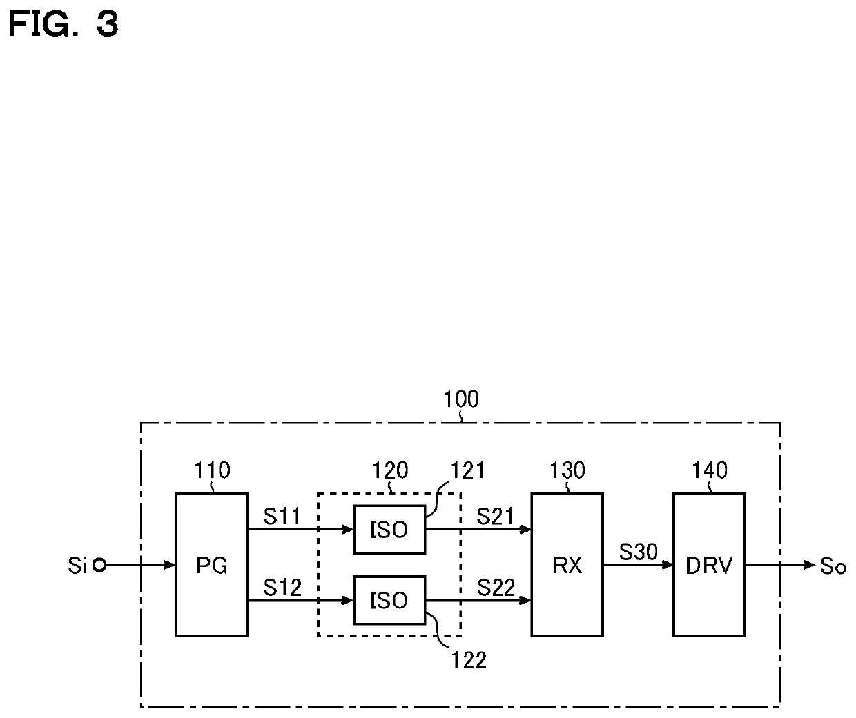
[0066]FIG. 3 is a diagram showing a first embodiment of a signal transfer device that can be used as, for example, the isolated gate drivers 41 to 44. The signal transfer device 100 of this embodiment includes a pulse generation circuit 110, an isolation circuit 120, a pulse reception circuit 130, and an output drive circuit 140.

[0067]The pulse generation circuit 110 generates transmission pulse signals S11 and S12 according to an input signal Si. More specifically, the pulse generation circuit 110, when notifying that the input signal Si is at high level, pulse-drives the transmission pulse signal S11 (outputs as the transmission pulse signal S11 a single pulse or several pulses) and, when notifying that the input signal Si is at low level, pulse-drives the transmission pulse signal S12 (outputs as the transmission pulse signal S12 a single pulse or several pulses). That is, the pulse generation circuit 110 pulse-drives one of the transmissi...

second embodiment

Signal Transfer Device (Second Embodiment)

[0101]FIG. 7 is a diagram showing a second embodiment of the signal transfer device 100. The signal transfer device 100 of this embodiment, while being based on the first embodiment (FIG. 3) described previously, has the pulse generation circuit 110, the isolation circuit 120, and the pulse reception circuit 130 implemented with specific circuit configurations respectively as a means for achieving signal transfer in a multiple transmission-reception system. It should be noted that such a signal transfer device 100 for a multiple transmission-reception system does not necessarily presuppose application to the isolated gate drivers 41 to 44.

[0102]Moreover, in the signal transfer device 100 of this embodiment, a noise cancel circuit 150 is provided between the isolation circuit 120 and the pulse reception circuit 130. In the diagram, the output drive circuit 140 is omitted from illustration, and whether to include or omit it is of free choice. ...

third embodiment

Signal Transfer Device (Third Embodiment)

[0155]FIG. 11 is a diagram showing a third embodiment of the signal transfer device 100. The signal transfer device 100 of this embodiment, while being based on the second embodiment (FIG. 7) described previously, uses, as the reset signal RSTH, not the logically inverted signal of the mask signal MSKH, but the logically inverted signal of the clock signal CLKL, and uses, as the reset signal RSTL, not the logically inverted signal of the mask signal MSKL, but the logically inverted signal of the clock signal CLKH.

[0156]Specifically, when a pulse is generated in the clock signal CLKL, the count value CNTH of the counter 132 is set back to the initial value (=0); when a pulse is generated in the clock signal CLKH, the count value CNTL of the counter 133 is set back to the initial value (=0).

[0157]As mentioned previously, even when in-phase noise occurs in both the input signals INH and INL, owing to the action of the noise cancel circuit 150, n...


PUM


Abstract

A pulse generation circuit has: an edge detector detecting a pulse edge in an input signal to generate edge detection signals; a clock generator generating a clock signal according to the edge detection signals; a frequency divider dividing the frequency of the clock signal to generate a frequency-divided clock signal; an input pad for receiving a test mode switch signal from a tester; and an output pad for outputting the frequency-divided clock signal to the tester. The edge detector can generate the edge detection signals by detecting a pulse edge not in the input signal but in the clock signal or in the inverted clock signal obtained by inverting the logic level of the clock signal when the test mode switch signal is being fed in. The signal delay time in the edge detector is adjustable according to the period of the frequency-divided clock signal as measured by the tester.

Description

[0001]This application is based on the following Japanese patent applications, the contents of which are hereby incorporated by reference:(1) Japanese Patent Application published as No. 2018-126606 (filed on Jul. 3, 2018)(2) Japanese Patent Application published as No. 2018-126608 (filed on Jul. 3, 2018)(3) Japanese Patent Application published as No. 2018-126610 (filed on Jul. 3, 2018)BACKGROUND OF THE INVENTION1. Field of the Invention[0002]The invention disclosed herein relates to signal transfer devices.2. Description of Related Art[0003]Conventionally, signal transfer devices that transfer pulse signals while isolating between input and output are used in a variety of applications (in power supply devices, motor driving devices, and the like).[0004]Examples of conventional technology related to what is mentioned above are seen in Japanese Patent Applications published as Nos. 2014-007502, 2018-014549, 2014-003515, and 2010-010762.[0005]First Problem: Inconveniently, convention...

Claims


Application Information

Patent Timeline
Patent Type & Authority Patents(United States)
IPC IPC(8): H03K5/22H03K5/1252H03K3/01H03K3/037G06F1/06H03K21/00G06F1/08H03K19/20
CPCH03K21/00G06F1/08H03K5/1252G06F1/06H03K3/01H03K19/20H03K3/037
Inventor ARIMURA, MASAHIKO
Owner ROHM CO LTD
Why Eureka
Try Eureka