
Method and system for correcting the frequency or phase of a local signal generated using a local oscillator

a local signal and frequency correction technology, applied in surveying and navigation, instruments, navigation instruments, etc., can solve the problems of weak signals that require a long integration period, local oscillators are relatively unstable, and are impractical for consumer products such as mobile phones

Active Publication Date: 2020-10-27
FOCAL POINT POSITIONING
View PDF33 Cites 2 Cited by
  • Summary
  • Abstract
  • Description
  • Claims
  • Application Information

AI Technical Summary

Benefits of technology

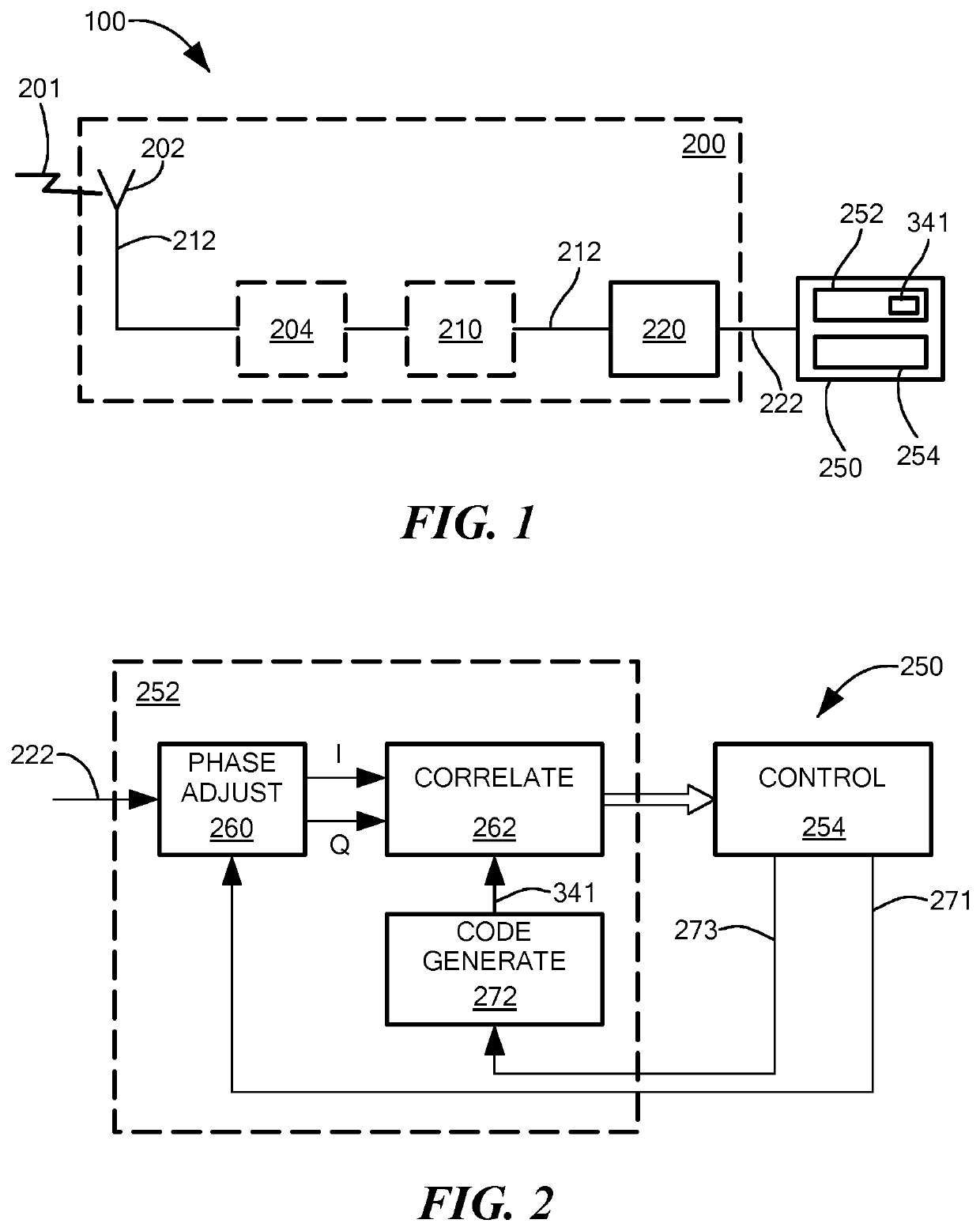
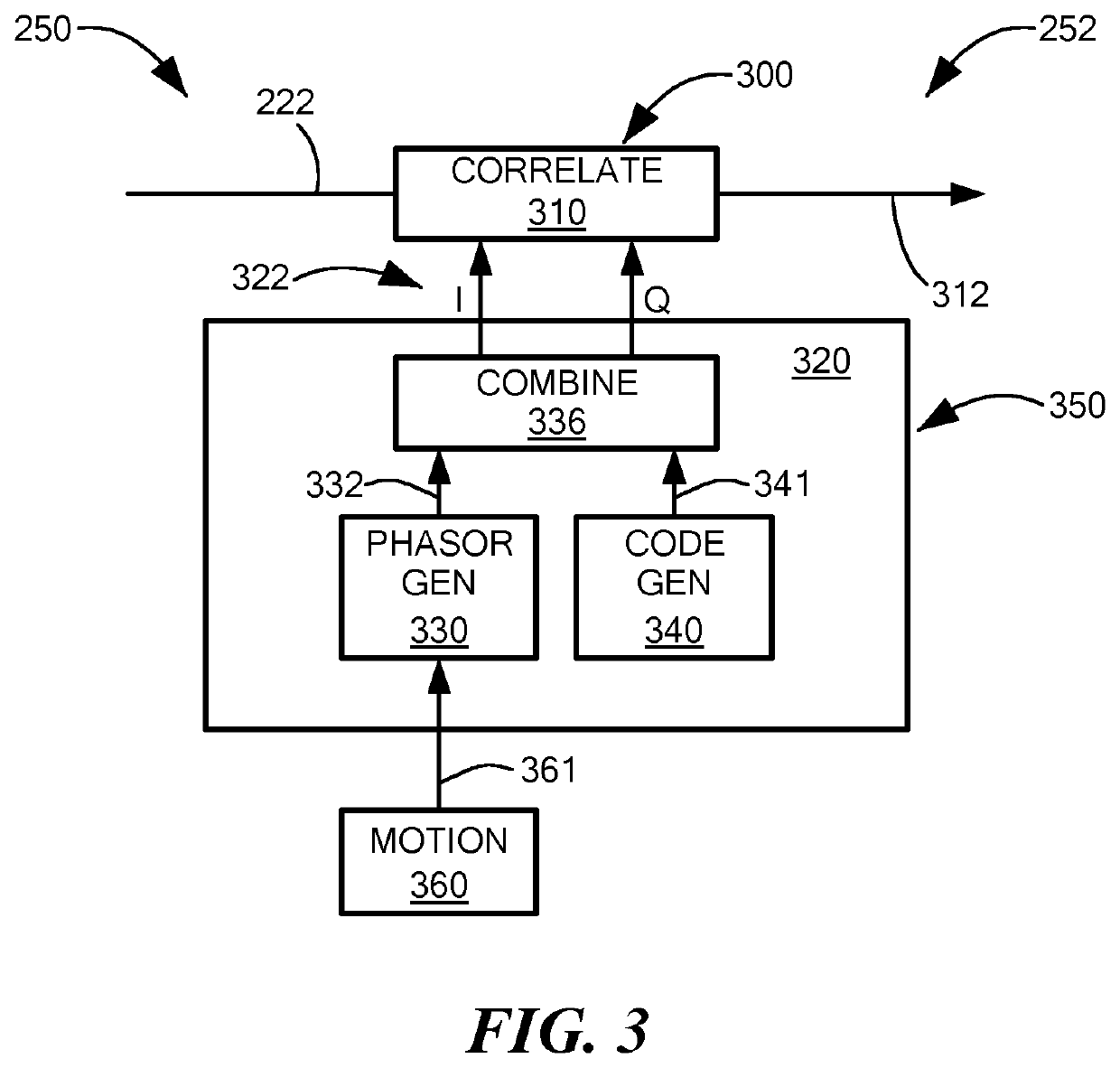
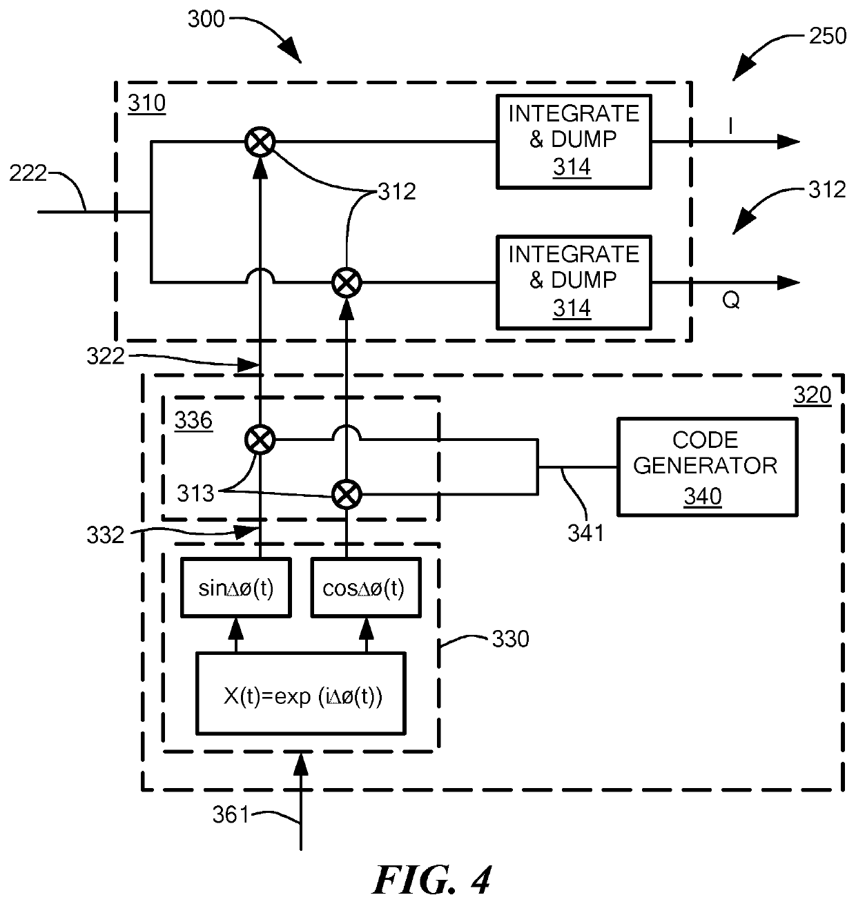
[0009]In this way, the positioning system can remove errors introduced to the first local signal by instabilities in the local oscillator. Errors in the local oscillator can be isolated by removing the effects introduced to the received phase or the received frequency based on the relative movement of the receiver and the first reference source in the first reference direction. The local oscillator of the positioning system can therefore be locked to the local oscillator of the first reference source. This can be achieved even with a moving receiver because the motion module can eliminate effects caused by this local movement. By improving the accuracy of the local signal generated using the local oscillator a moving receiver can provide longer coherent integration of signals than would otherwise be possible. This means that, following correction to the frequency or phase of the local oscillator, the sensitivity of the receiver is significantly improved so that weaker positioning signals can be detected and used in positioning calculations.
[0044]At the second time, the motion compensation unit may be configured to compare the measured or assumed movement of the receiver at the first time with a measured or assumed movement of the receiver at the second time and, based on the comparison, provide motion compensation of at least one of the local signal, the received positioning signal and the correlation signal, based on the stored parameter or set of parameters. The movement of the receiver is often highly similar in different time periods. In a car, speed and bearing may be similar over time periods separated by a few seconds, especially in motorway conditions. Similarly, when the receiver is held by a jogger it will typically have a predictable pattern of movement; if the speed and bearing of the user does not change, the pattern may be repeated in time periods separated by a few seconds or more. In these situations the comparison may indicate a substantial similarity between movement at the first time and movement at the second time. Thus, it may be efficient for the receiver to re-use parameters such as vectors or phasors that were calculated for the earlier epoch. These parameters may be used to provide effective motion compensation at the second time, while reducing computational load and preserving battery resources.

Problems solved by technology

These local oscillators are relatively unstable in comparison to high cost local oscillators such as atomic clocks.
However, for many positioning applications this is not especially important since absolute time is calibrated in GNSS positioning calculations, and even low cost local oscillators can achieve stability over time periods that are longer than the time period over which signals are coherently integrated.
These weak signals require a long integration period if they are to be detected with sufficient strength to be used in positioning calculations.
This is possible for high cost positioning devices, but it is impractical for consumer products such as mobile phones.
However, it is not effective when applied to consumer products such as mobile phones that are free to move around, since this local movement can be the source of other errors.
This is especially important in challenging positioning environments such as urban canyons.
There may be high accelerations and high forces on the receiver during these time periods, which can cause temporary instabilities such that the local oscillator is less reliable.
Conventionally phase changes in the received positioning signal caused by changes in the line-of-sight path between the receiver and the remote source were viewed as a nuisance that reduced positioning accuracy.
The local signal may be similarly complex.
In practice this can produce an accurate result because it works at the radio sampling frequency, although it may be computationally intensive.
Positioning using GNSS positioning devices produces a number of difficulties indoors, where signals are weak, and in urban canyons, where there can be multipath signals.

Method used


Image

  • Method and system for correcting the frequency or phase of a local signal generated using a local oscillator
  • Method and system for correcting the frequency or phase of a local signal generated using a local oscillator
  • Method and system for correcting the frequency or phase of a local signal generated using a local oscillator

Examples


Embodiment Construction

[0071]FIG. 20 is a schematic view of a user 2 holding a positioning device 4 in an urban environment (to represent a challenging positioning environment). In this example the positioning device 4 can receive signals from first, second and third positioning satellites 6, 8, 10. The positioning device 4 can also receive signals from a terrestrial transmitter 12. The signal from the satellite 6 and the terrestrial transmitter 12 are received through buildings. These signals are attenuated by the material of the buildings, which means that the signal strengths can be low, especially for the signals received from the distant satellite 6. In some instances the signal strengths may be too low for use in positioning calculations, unless the signals are integrated over a relatively long period of time (perhaps as much as 1 second, or longer). Received signals may also be subject to multipath, which represents an additional complication. In FIG. 20 the signals from satellites 8, 10 can be rec...


PUM


Abstract

A positioning device (4) is disclosed comprising at least one antenna (14, 16) for receiving ranging signals, such as GNSS signals. The device comprises a local oscillator (18) for providing a local frequency or phase reference and an inertial sensor (22) for measuring a movement of the device. A processor (36) is provided for performing calculations. The device can receive a first reference signal at a known or predictable frequency or phase. A local oscillator offset determination module (26) is provided to calculate an offset to the received frequency or the received phase based on the movement of the receiver in the direction of the first reference source. A local signal generator (28) can then use the local frequency or phase reference from the local oscillator (18), and the offset calculated by the local oscillator offset determination module (26), to provide a local signal using a local signal generator (28). The local signal can be correlated against a received ranging signal for use in positioning calculations performed by a positioning calculator (34).

Description

[0001]This application claims priority from United Kingdom Patent Application GB 1710894.5, filed Jul. 6, 2017, which is incorporated herein by reference in its entirety.TECHNICAL FIELD[0002]The present invention relates to a positioning system and a method performed in a positioning system for improving the frequency stability of a local signal generated using a local oscillator.BACKGROUND ART[0003]A local oscillator is an important component in a positioning system, such as a GNSS receiver. Local oscillators are often low cost components, including, for example, quartz crystals. These local oscillators are relatively unstable in comparison to high cost local oscillators such as atomic clocks. However, for many positioning applications this is not especially important since absolute time is calibrated in GNSS positioning calculations, and even low cost local oscillators can achieve stability over time periods that are longer than the time period over which signals are coherently in...

Claims


Application Information

Patent Timeline
Patent Type & Authority Patents(United States)
IPC IPC(8): G01S19/29G01S19/22G01S19/24G01C21/16G01S19/26G01S19/23G01S19/05
CPCG01S19/29G01S19/26G01S19/235G01S19/22G01S19/05G01S19/246G01C21/165G01C21/26G01S5/0247G01S19/23G01S19/24G01S19/31G01S19/47
Inventor FARAGHER, RAMSEYCOURONNEAU, NICOLASCROCKETT, ROBERT MARKDUFFETT-SMITH, PETER
Owner FOCAL POINT POSITIONING
Learn More