

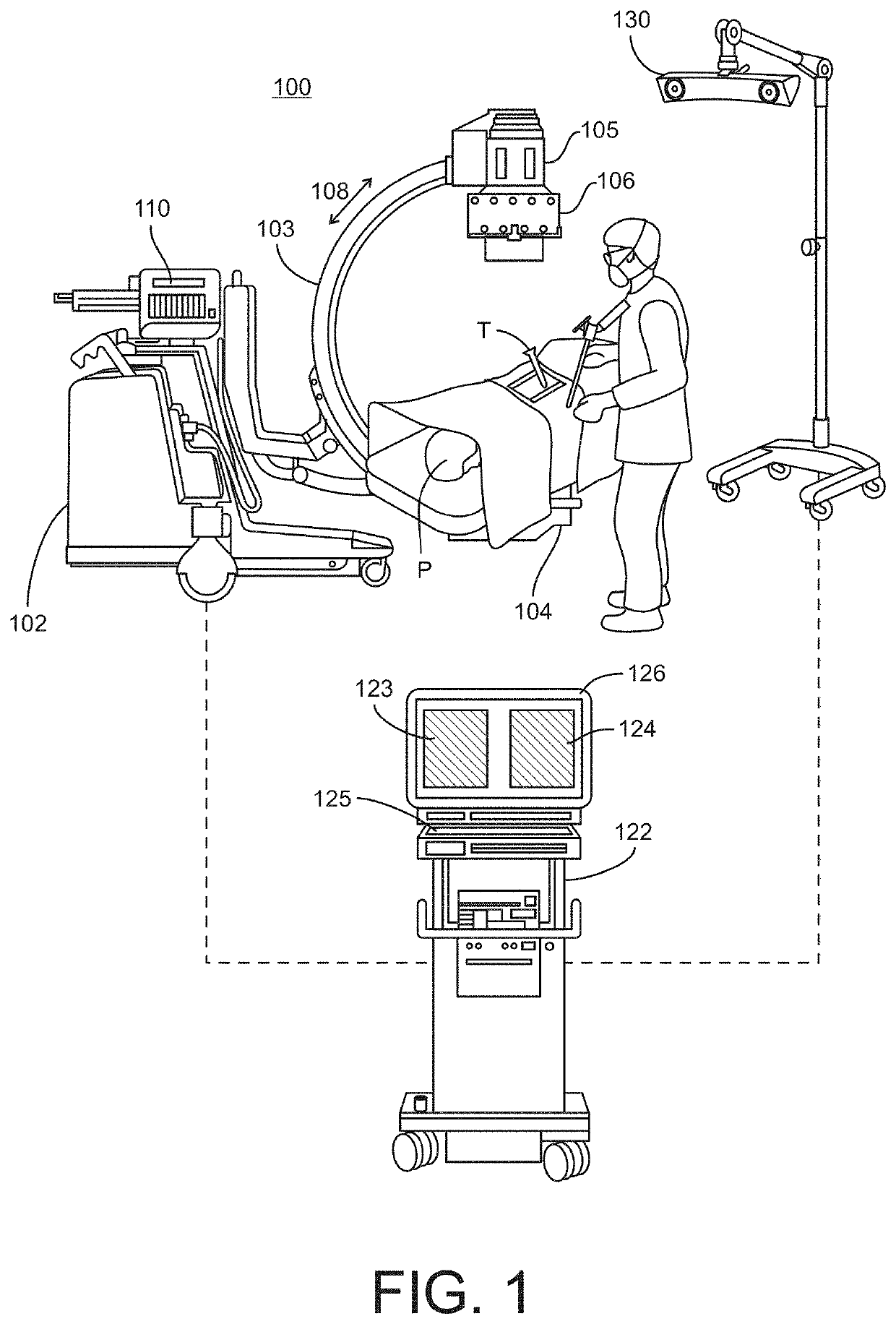
Imaging system and method for image localization of effecters during a medical procedure
a technology of effecters and imaging systems, applied in the field of image localization systems and methods for effecters during medical procedures, can solve the problems of increasing the amount of radiation, reducing the resolution of the image being obtained, and affecting the patient's overall radiation exposure, so as to achieve a high degree of accuracy
- Summary
- Abstract
- Description
- Claims
- Application Information
AI Technical Summary
Benefits of technology
Problems solved by technology
Method used
Image

Examples
Embodiment Construction
[0127]For the purposes of promoting an understanding of the principles of the disclosure, reference will now be made to the embodiments illustrated in the drawings and described in the following written specification. It is understood that no limitation to the scope of the disclosure is thereby intended. It is further understood that the present disclosure includes any alterations and modifications to the illustrated embodiments and includes further applications of the principles disclosed herein as would normally occur to one skilled in the art to which this disclosure pertains.
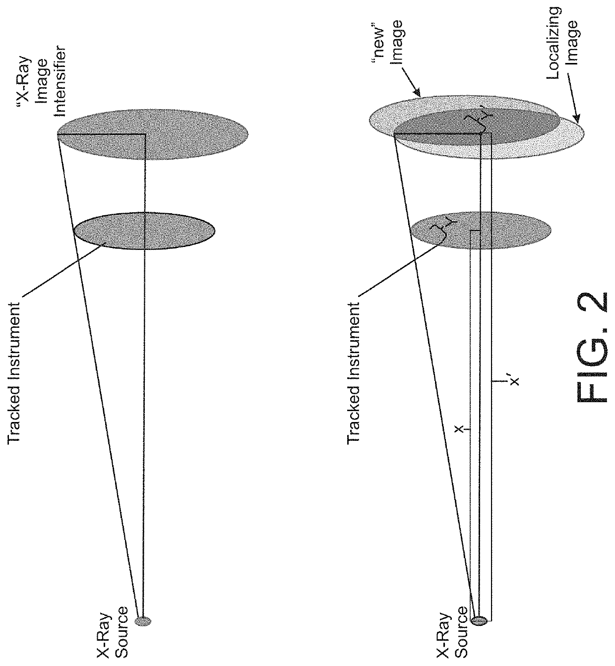
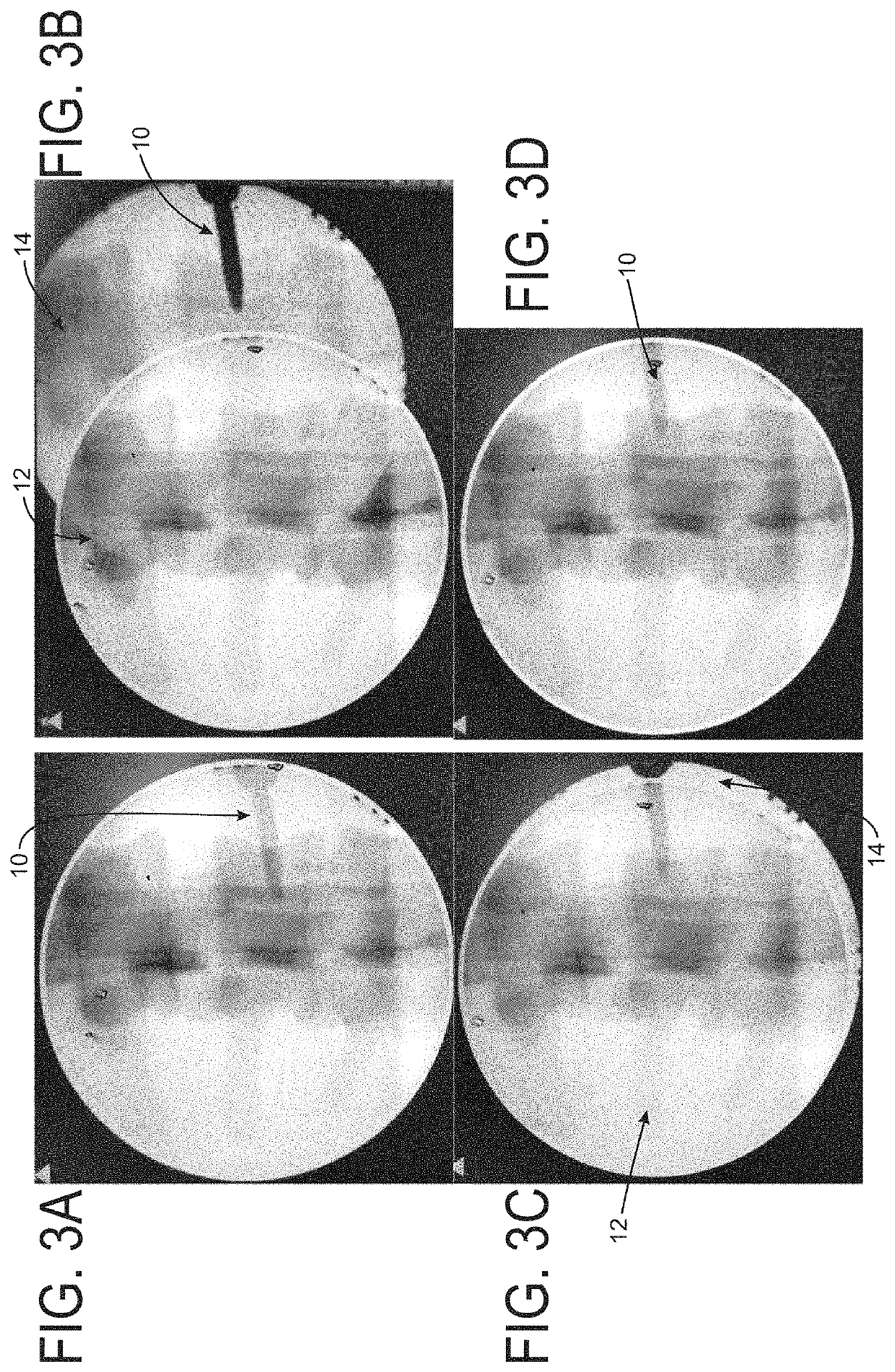
[0128]According to one aspect of the invention, the process begins with taking an image of the anatomy to be addressed surgically. Typically this “localizing shot” or “baseline image” does not contain the radio-dense effecter (e.g.—screw, cannula, guidewire, instrument, etc.) that is to be moved / adjusted, although in one embodiment a single image containing the effecter can be used. The image processing devi...
PUM
 Abstract
Description
Claims
Application Information