Device and method for determining proper screw or implant size during orthopedic surgery

a technology for determining the size of the screw or the implant, applied in the field of orthopedic surgery, can solve the problems of limiting the type of feature of the user, affecting the healing of patients, and insufficient rough estimates, so as to achieve accurate and precise measurement distances inside the body, prevent damage to sensitive tissues, and prevent patients from healing

Active Publication Date: 2020-11-24
SURGENTEC LLC
View PDF26 Cites 0 Cited by
  • Summary
  • Abstract
  • Description
  • Claims
  • Application Information

AI Technical Summary

Benefits of technology

[0007]The devices and methods described herein allow for the measurement of objects and distances inside the patient's body when used in tandem with x-ray or fluoroscopy imaging during orthopedic surgeries. Also, the devices and methods described herein act as a guide to accurately insert an instrument or implant, in the correct orientation, to the surgical site.
[0010]In one embodiment, the guidewire is made of nitinol, also known as nickel titanium. Nitinol is radiopaque and an excellent alloy for k-wires or guide wires because of its strength, biocompatibility, and kink resistant properties. In one embodiment, the nitinol wire has a measurement segment which comprises one or more visualization windows. These visualization windows are holes in the wire body that can be visualized while inside the body when used in tandem with x-ray or fluoroscopy. In one embodiment, the visualization windows are oval in shape and have a length of 6.6 DW≥LVW≥0.7 DW, wherein DW=Diameter of the wire body and LVW=Length of the visualization window. In a wire with a diameter of 0.060 inches, this equates to a range of around 1 mm-10 mm which is an important size. Through multiple test methods, it was determined that the nitinol guidewire won't work for its intended use when the length of the visualization windows are outside that range. When the visualization window's length is smaller than 0.7 DW the side wall of the visualization window is too stiff and brittle. A brittle wire means an elevated risk of breaking and risk to patient's safety. On the other hand, when the visualization window's length is greater than 6.6 DW, the side wall of the window becomes too flexible and causes the wire to bend too easily as it is inserted into the body. Also in one embodiment, there may be an alignment aid on the proximal tip of the guide wire. This alignment aid allows the user to line up the visualization windows so that the window is in the beam of the x-ray or fluoroscopy. It should be noted that in other embodiments, the visualization windows may be any shape and size, including but not limited to oval, triangular, square, rectangular, trapezoidal, pentagonal, hexagonal, or octagonal. In other embodiments, the visualization windows may be variably aligned in any access so that they may be visualized when the fluoroscopy or x-ray image is taken at any angle.
[0011]In some embodiments, the guidewire may be annealed or heat treated to change several of its properties including but not limited to the flexibility, strength, shape, color, biocompatibility, or chemical structure. Annealing can be a key manufacturing process to achieve the desired characteristics for differing surgeries. In some embodiments, different heating and cooling process may be used to make the guidewire more stiff, flexible, permanently bent in a given direction, etc.

Problems solved by technology

In some cases, this type of feature may be limiting to the user if they need to go deeper than what the wire allows.
Some guidewires available today can be visualized inside the patient's body but they only provide users with information about relative position and orientation of the wire and surrounding objects.
However, these wires don't provide precise measurements because they do not allow the user to measure distances between structures or objects directly inside the patient's body.
In a field where a millimeter could mean the difference between a successful surgery and a disaster, a rough estimate is not enough.
Choosing the correct screw size isn't easy and errors in this process could be detrimental.
A screw too short won't be stable and in turn may hinder the patient from healing.
On the other hand, a screw too long can have life-threatening consequences such as nerve damage or hemorrhage.
This causes further trauma to the patient, slowing their recovery, and can decreases the chances of the screw holding.
This process is called explanting and it can cost hospitals tens of thousands of dollars annually.
In addition, many fluoroscopy images are taken each time a surgeon attempts to place a screw, exposing both the surgeon and patient to potentially harmful radiation.
Through multiple test methods, it was determined that the nitinol guidewire won't work for its intended use when the length of the visualization windows are outside that range.
When the visualization window's length is smaller than 0.7 DW the side wall of the visualization window is too stiff and brittle.
A brittle wire means an elevated risk of breaking and risk to patient's safety.
On the other hand, when the visualization window's length is greater than 6.6 DW, the side wall of the window becomes too flexible and causes the wire to bend too easily as it is inserted into the body.
When the visualization windows have a width less than 10% of the wire's diameter, the walls of the wire body that surround the visualization window are too stiff and brittle and can snap under significant pressure or flexing.
Also, visualization windows less than 10% of the wire's diameter are difficult to visualize under fluoroscopy or x-ray when the wire diameter is an appropriate size for many orthopedic surgeries.
A visualization window less than or equal to 0.0062″ would be very difficult to visualize.

Method used


Image

  • Device and method for determining proper screw or implant size during orthopedic surgery
  • Device and method for determining proper screw or implant size during orthopedic surgery
  • Device and method for determining proper screw or implant size during orthopedic surgery

Examples


Embodiment Construction

[0031]Although certain embodiments and examples are described below, those of skill in the art will appreciate that the disclosure extends beyond the specifically disclosed embodiments and / or uses and obvious modifications and equivalents thereof. Thus, it is intended that the scope of the disclosure herein disclosed should not be limited by any particular embodiments described below.

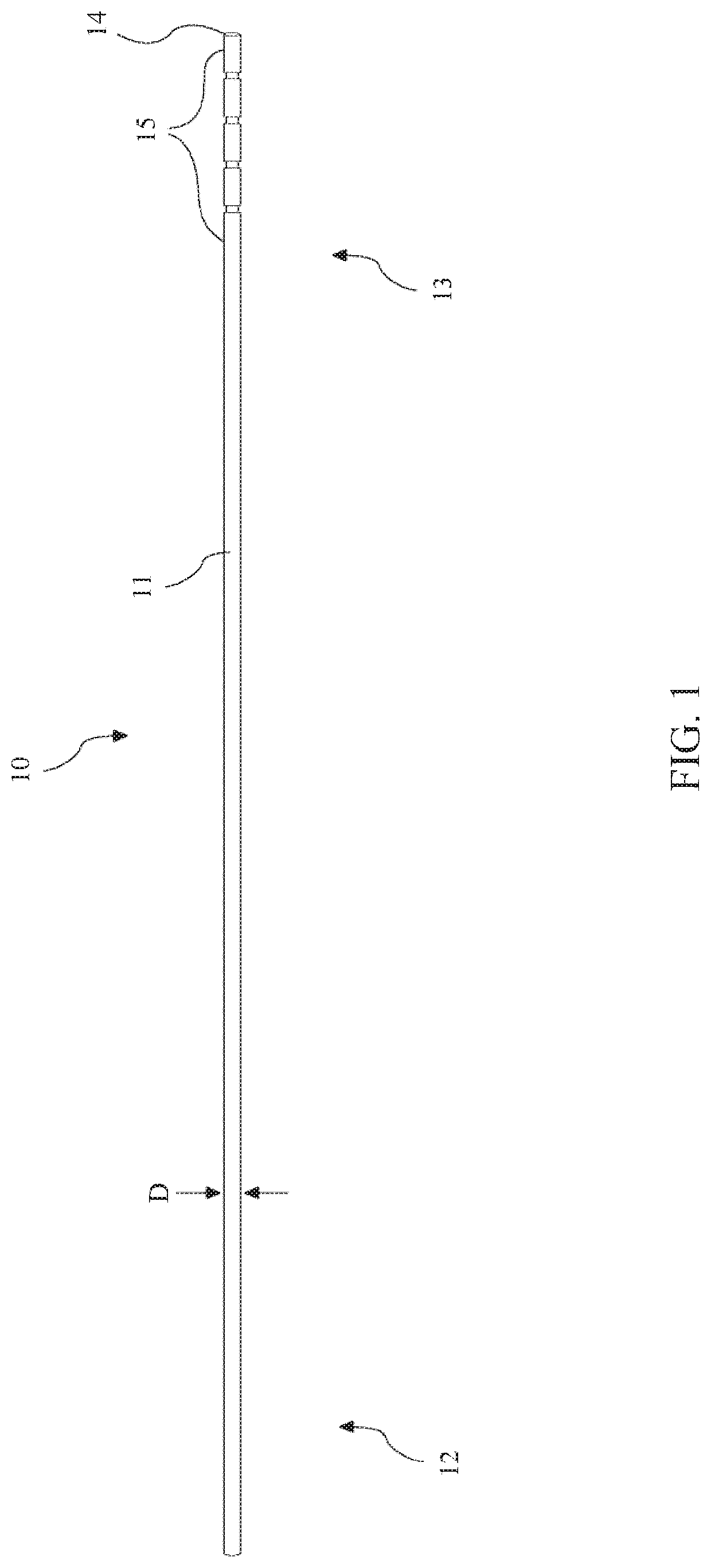
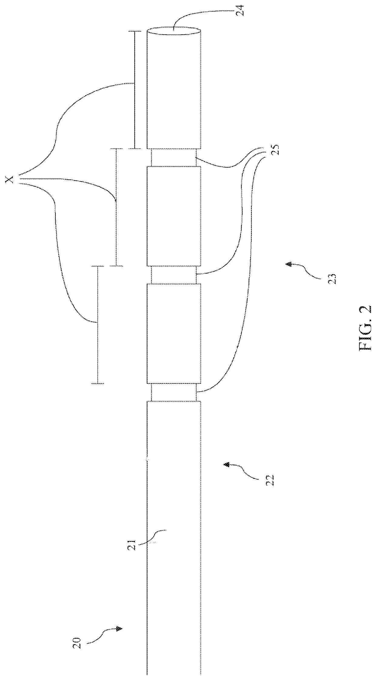
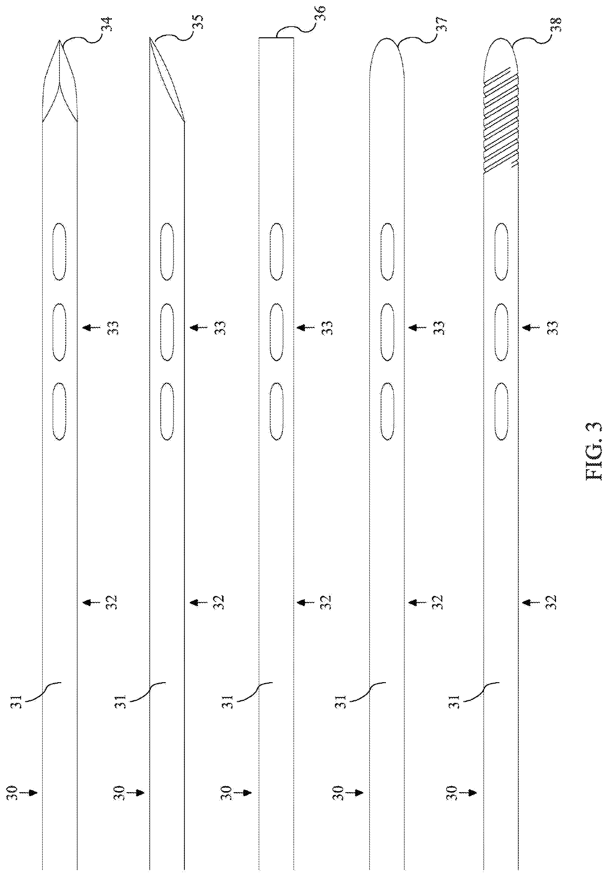
[0032]The present disclosure is directed to methods and devices for a guidewire, often referred to as a k-wire, for orthopedic surgeries. The devices and methods described herein allow for the measurement of objects and distances inside a patient's body when used in tandem with x-ray or fluoroscopy imaging during orthopedic surgeries. The devices and methods described herein can also act as a guide to accurately insert an instrument or implant, in the correct orientation, to a surgical site by passing the instrument or implant over the guide wire. The devices described herein can be used in junction wit...


PUM


Abstract

The devices and methods described herein refer to a guidewire, sometimes referred to as a K-wire, for use during varying orthopedic surgeries. The guidewire allows for the measurement of objects and distances inside the patient's body when used in tandem with x-ray or fluoroscopy imaging. Also, the devices and methods described herein act as a guide to accurately insert an instrument or implant, in the correct orientation, to the surgical site. The guidewire comprises a measurement segment that comprises one or more markers placed at known distances from the distal end of the guidewire. The markers, when used in tandem with fluoroscopy and / or x-ray imaging, provide users with a reference for measuring objects and distances inside the body. The markers can have many possible designs or configurations such as, but not limited to, visualization windows, grooves, notches, and / or material inserts.

Description

BACKGROUNDField[0001]The present disclosure generally relates to devices and methods for orthopedic surgery. More particularly, the present disclosure relates to devices and methods used to measure distances within and to aid in the insertion of instruments and implants into the body.Description of the Related Art[0002]Guidewires are used in many orthopedic procedures, especially in minimally invasive surgical procedures. In one example surgical procedure, a Jamshidi needle is used to create a pilot hole in the pedicle of a spinal vertebra. A guidewire is then inserted into the pilot hole and acts as a guide for pedicle screw placement to avoid injuring sensitive vascular or nerve tissue.[0003]Currently available guidewires are made from many types of materials such as stainless steel, gold, platinum, titanium, tungsten, nickel, and alloys of such materials. Different materials provide for differences in stiffness, flexibility, and visual properties when under fluoroscopy or radiogr...

Claims


Application Information

Patent Timeline
Patent Type & Authority Patents(United States)
IPC IPC(8): A61B6/12A61B6/00A61B17/84A61B17/88A61B17/92A61B90/00A61B17/34A61B17/00
CPCA61B6/12A61B6/481A61B17/848A61B17/8897A61B6/487A61B2090/392A61B2090/3966A61B2090/061A61B2017/00867A61B17/3472A61B2090/3983A61B17/92A61B17/8861
Inventor SHOUP, ANDREWBIRO, SEANBIRO, WALTERGREENHALGH, TRAVIS
Owner SURGENTEC LLC
Why Eureka
Try Eureka