Method for full-field measurement using dynamic laser doppler imaging

a dynamic laser and imaging technology, applied in lasers, laser details, instruments, etc., can solve the problems of limiting the application scope, the carrier frequency introduced by these methods is difficult to be adjusted anymore, and the system cannot directly measure the optical signal, so as to improve the measurement accuracy and range, and simplify the detection system. , the effect of strong ability to avoid disturban

Active Publication Date: 2021-01-05
BEIJING JIAOTONG UNIV
View PDF4 Cites 1 Cited by
  • Summary
  • Abstract
  • Description
  • Claims
  • Application Information

AI Technical Summary

Benefits of technology

[0006]The object of the invention is to provide a method for full-field measurement using laser Doppler imaging, which combines time sequence interferometry and laser Doppler technology to realize the real-time and full field heterodyne imaging measurement of the detected object and simplifies the detection system, solving the problem that only the point measurement of laser Doppler technology can be realized at present. It is helpful to improve the measurement accuracy and range, and then the accurate real-time and full-field measurement can be carried out. It also has a strong ability to avoid disturbance and a wide application range.
[0016]The invention combines the advantages of time series interferometry and laser Doppler technology, solving the problem that only a point's deformation can be measured by the laser Doppler technology at present and realizing the real-time heterodyne imaging full field measurement of the measured object. The invention simplifies the detection system and greatly improves the accuracy and range of measurement. It has the characteristics of real-time, full field and accurate measurement, and the properties of strong anti-interference and wide application range.
[0017]According to the invention, the width of heterodyne frequency shift, such as Doppler shift, carries the information of measured physical quantities. Through the conventional phase extraction methods, such as spectrum analysis, Fourier transform and Wavelet transform, the phase information can be obtained, so as to obtain the measured physical quantities. Since the frequency shift between the two beams is introduced by the invention, even if the beat frequency has a slow drift, the relative phase of the beat frequency can still be accurately measured. In the heterodyne system, it is very important to obtain a stable and reliable heterodyne carrier frequency, which is directly related to the stability and measurement accuracy of the system.
[0018]According to the present invention, the new technology of Doppler imaging full-field measurement is based on the double transverse electro-optic effect. There is no moving mechanical part in the system. The carrier frequency of the system can be adjusted and the value of the heterodyne carrier frequency depends on the rotational angular frequency of the driving electric field. Because the value of the carrier frequency is only related to the frequency of the supply signal which drives the power, the carrier frequency can be obtained from the order of Hz to the order of GHz so that the carrier frequency can be widely adjusted. By setting the appropriate electric field frequencies, the generated carrier frequencies can be well adapted to various detectors' sampling frequencies. From low frequency to high frequency, it can meet the requirements of the different measured objects under the different conditions. With this heterodyne carrier frequency technology, the dynamic full-field imaging is possible.
[0019]According to the present invention, dynamic full-field imaging is realized, and the full-field imaging technology based on the time series is implemented by combining the heterodyne carrier frequency device with the double transverse electro-optic effects. Using the detector of the surface array to collect the full field interference signal of the time series, the signal data are transmitted to the computer. Next Fourier transform or Wavelet transform the light intensity of each point on the time axis, so that the truncated phase can be obtained. Then the phase unwrapping process will be carried out by the unwrapping technique, so that every point on the measured object changes with time. Finally, the phase information can be calculated so that the full field surface deformation of the measured object based on time series are also calculated, which can provide a powerful means for non-destructive optical inspection and other technologies.

Problems solved by technology

However, due to the restriction of the detector response frequency, the system can't directly measure the optical signal.
However, the heterodyne carrier frequency introduced by dual frequency laser, acousto-optic modulator and magneto-optical effect are in the range of several MHz to tens of MHz, which are too high for the frame rate of the detector array devices in current time, hence, only point measuring rather than full field measuring in real time can be realized by those methods.
On the other hand, the carrier frequency introduced by these methods are hard to be adjusted anymore once these devices are made of, which limits the application scope.
The carrier frequency introduced by the mechanical heterodyne carrier device can be flexibly adjusted in the low frequency region, but it is unstable due to the vibration of the drive motor, in addition, the frequency difference produced by this method is small due to the limitation of the rotating speed of the motor.

Method used


Image

  • Method for full-field measurement using dynamic laser doppler imaging

Examples


Embodiment Construction

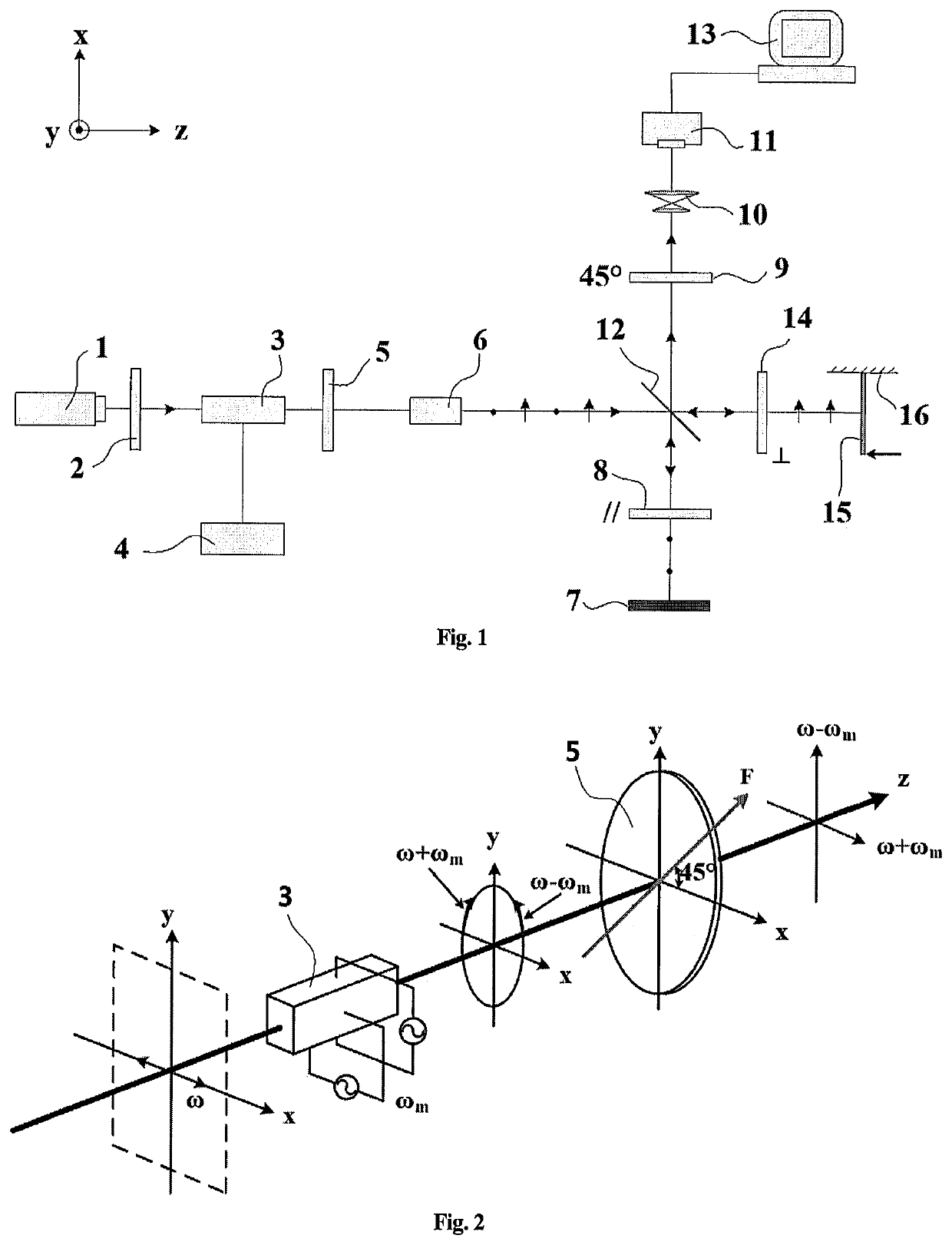
[0023]The following is a detailed description of the embodiment using the principle of the laser Doppler imaging full-field measurement as shown in FIGS. 1 and 2. It should be emphasized that the following description is just for an example and not intended to limit the scope and application of the present invention.

[0024]As shown in FIG. 1, the reference number 1 represents by laser diodes; the reference number 28, 9 and 14 represent the polarizers; the reference number 3 represents the lithium niobate crystal (LiNbO3); the reference number 4 represents the driving power of the lithium niobate crystal; the reference number 5 represents the quarter-wave plate; the reference number 6 represents the spatial filter; the reference number 7 represents the reference object; the reference number 10 represents the imaging system; the reference number 11 represents the CCD camera; the reference number 12 represents the beam splitter; the reference number 13 represents the computer; the refer...


PUM


Abstract

A method for full-field measurement using Doppler imaging, comprising the following steps: turning on a laser and adjusting the laser; adjusting a spatial filter to obtain circular laser spots having uniform intensity distribution; adjusting a quarter-wave plate and a whole polarizer in a system, and requiring two beams in a reference object and a measured object having different frequencies and perpendicular polarization directions; applying slight pressure to the measured object, setting a charge coupled device (CCD) camera into a continuous acquisition mode, observing interference fringes, and adjusting a light path so that the fringes are clear and visible; setting the sampling frequency, sampling time, captured image format and resolution size of the CCD camera; turning on a lithium niobate crystal drive power switch to produce a heterodyne carrier frequency; applying continuous equal pushing force to the measured object by means of piezoelectric ceramics (PZT) so as to make the measured object produce continuous bending deformation; controlling the CCD camera to sample using a computer, and collecting a set of time series light interference images along with the continuous deformation of the measured object; and processing the time series light intensity interference image to obtain a three-dimensional data module comprising continuous deformation of the measured objects distributed in time and space.

Description

FIELD OF THE INVENTION[0001]The present invention relates to a method for measuring a full-field by dynamic laser Doppler imaging, which belongs to the technical field of optical laser measurement.PRIOR ART[0002]It is a laser that makes a Doppler effect in acoustics develop into the field of optics. The laser Doppler effect is an effective method for deformation measurement. However, due to the restriction of the detector response frequency, the system can't directly measure the optical signal. Thus, the optical frequency difference technique must be applied to extract the deformation information from the low frequency interference signal. Combining optical Doppler effect with optical heterodyne interferometry, the so-called laser Doppler technology in the existing technology is formed.[0003]Laser Doppler technology has been proved to be a very useful technology. It has many advantages such as non-contact, high accuracy, wide measuring range, anti-electromagnetic interference, fast ...

Claims


Application Information

Patent Timeline
Patent Type & Authority Patents(United States)
IPC IPC(8): G01B9/02H01S3/10
CPCG01B9/02045H01S3/10053G01B9/02003G01B11/161H01S5/0085
Inventor GAO, ZHANQIN, JIEFENG, QIBOWANG, SHENGJIAWANG, XUYANG, SHANWEIGAO, CHENJIA
Owner BEIJING JIAOTONG UNIV
Why Eureka
Try Eureka