Eureka AIR delivers breakthrough ideas for toughest innovation challenges, trusted by R&D personnel around the world.

Method of controlling resolution of digital pulse width modulation

Active Publication Date: 2021-01-05
ASIAN POWER DEVICES
View PDF1 Cites 0 Cited by
  • Summary
  • Abstract
  • Description
  • Claims
  • Application Information

AI Technical Summary

Benefits of technology

The present patent discloses a method for controlling the resolution of digital pulse width modulation without increasing the maximum operating frequency of electronic components. This allows for easier adjustment of output resolution with minimal required adjustment range. The method improves the accuracy of the controllable resolution, reducing power components and improving the quality of the output signal. Additionally, the method helps disperse electromagnetic interference and reduce its influence on the output signal.

Problems solved by technology

However, analog circuits have many problems, such as control signals that are prone to drift over time, difficult to adjust, high power consumption, and easy to be disturbed by noise signal and environmental factors.
However, the electronic components suitable for high frequency are expensive, and consuming more power.
However, the dither method tends to produce higher output voltages and current ripples.
However, the conventional method is limited by the maximum operating frequency of the PWM period clock, and thus the accuracy of the controllable resolution cannot be improved.

Method used


Image

  • Method of controlling resolution of digital pulse width modulation
  • Method of controlling resolution of digital pulse width modulation
  • Method of controlling resolution of digital pulse width modulation

Examples


first embodiment

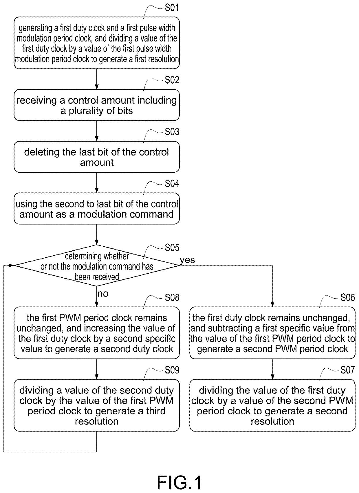
[0026]When the method of controlling a resolution of digital pulse width modulation in the present disclosure is used, for the digital pulse width modulation generator the first resolution is generated by dividing the value of the first duty clock by the value of the first PWM period clock. Basically, a PWM period clock of conventional method is fixed, so the resolution of conventional method is completely determined by the duty clock. The conventional method can only change the resolution by adjusting the duty clock. However, the conventional method is limited by the maximum operating frequency of the PWM period clock, and thus the accuracy of the controllable resolution cannot be improved. The first duty clock. and the first PWM period clock of the present disclosure are controlled by the modulation command. And without changing a maximum value of adjustable values of the first PWM period clock (i.e., the maximum operating frequency of the electronic components), can create the se...

second embodiment

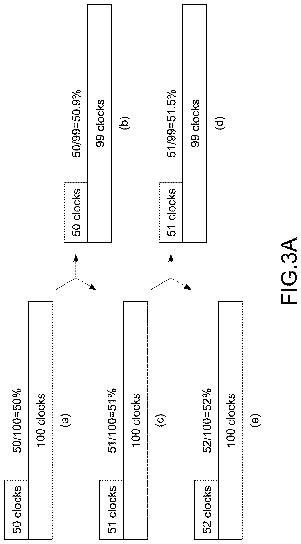
[0035]By analogy, based on (c) of the FIG. 3A, the resolution at the next stage is 51.5% within (d) of the FIG. 3A, and 52% within (e) of the FIG. 3A. the present disclosure creates a resolution of 50.9% and 51.5% compared to the conventional method without increasing the maximum operating frequency of the DPWM generator. The conventional method can only provide the resolution is 50%, 51% and 52%.

[0036]As shown in the FIG. 3B, the third embodiment of the present disclosure is substantially the same as the second embodiment described above, except that the first specific value and the second specific value both are 2 clocks.

[0037]When confirming that the modulation command has not been received, the first PWM period clock (i.e., 100 clocks) remains unchanged (i.e., the maximum operating frequency of the DPWM generator is maintained), increasing the value of the first duty clock (i.e., 50 clocks) by a second specific value (i.e., 2 clocks) to generate a second duty clock (i.e., 52 clo...

third embodiment

[0039]By analogy, based on (c) of the FIG. 3B, the resolution at the next stage is 53.06% within (d) of the FIG. 3B, and 54% within (e) of the FIG. 3B. the present disclosure creates a resolution of 51.02% and 53.06% compared to the conventional method without increasing the maximum operating frequency of the DPWM generator. The conventional method can only provide the resolution is 50%, 52% and 54%.

[0040]Please refer to FIGS. 4A and FIG. 4B. The FIG. 4A is a schematic diagram of a fourth embodiment of the method of controlling a resolution of a digital pulse width modulation of the present disclosure. The FIG. 4B is a schematic diagram of a fifth embodiment of the method of controlling a resolution of a digital pulse width modulation of the present disclosure.

[0041]As shown in the FIG. 4A, the fourth embodiment of the present disclosure is substantially the same as the first embodiment described above, except that the first duty clock is 80 clocks.

[0042]When confirming that the mod...


PUM


Abstract

A method of controlling a resolution of digital pulse width modulation is applied to a digital pulse width modulation generator. The method is to divide a value of a first duty clock by a value of a first pulse width modulation period clock to generate a first resolution. And then, if it is confirmed that a modulation command has been received, a second resolution is generated, and if it is confirmed that the modulation command is not received, a third resolution is generated. The second resolution is greater than the first resolution, and the second resolution is less than the third resolution.

Description

BACKGROUNDTechnical Field[0001]The present disclosure relates to a method of controlling a resolution, and more particularly to a method of controlling a resolution of a digital pulse width modulation applied to a digital pulse width modulation generator.Description of Related Art[0002]The statements in this section merely provide background information related to the present disclosure and do not necessarily constitute prior art.[0003]In analog circuits, a value of an analog signal may be smoothly changed, almost any value can be chosen for a magnitude of time and value, an input and an output also vary linearly. However, analog circuits have many problems, such as control signals that are prone to drift over time, difficult to adjust, high power consumption, and easy to be disturbed by noise signal and environmental factors. Unlike analog circuits, digital circuits take values within a predetermined range, outputs at any time can only be ON (or call high level) or OFF (or call low...

Claims


Application Information

Patent Timeline
IPC IPC(8): H03K7/08H02M3/157H03M3/00
CPCH03K7/08H02M3/157H03M3/506
Inventor YAU, YEU-TORNGHUNG, TSUNG-LIANG
Owner ASIAN POWER DEVICES
Why Eureka
Eureka Blog
Learn More