
Three-dimensional, knitted, multi-spectral electro-magnetic detection resistant, camouflaging textile

a technology of electro-magnetic detection and camouflage textiles, applied in knitting, ornamental textile articles, weaving, etc., can solve the problems of increasing the likelihood of detection by observers using thermal imaging sensors, not always providing effective concealment by attenuating thermal signatures, and becoming more difficult for qualitatively and quantitatively to detect and identify camouflaged subjects. , to achieve the effect of minimizing detection and being easy to handl

Inactive Publication Date: 2021-01-26
TELEDYNE BROWN ENG A DIV OF TELEDYNE
View PDF18 Cites 1 Cited by
  • Summary
  • Abstract
  • Description
  • Claims
  • Application Information

AI Technical Summary

Benefits of technology

This patent describes a new camouflage material that can be used in a variety of environments and is effective at concealing the object's presence in the visual, infrared, and radio frequency spectrums. The material is lightweight and has a uniform structure that makes it easy to transport and handle in the field. It uses a special pattern of fibers to match the surroundings and minimize visual observation. The invention also includes a means for reducing detection by RF sensors. The invention's unique feature is the use of geometry of composite fabrics, which takes into account the shape factor and radiant area to control thermal camouflage. This material can also be combined with low emissivity materials for enhanced concealment.

Problems solved by technology

As a result, it becomes more difficult for an observer qualitatively and quantitatively to detect and identify the camouflaged subjects.
While the EM camouflaging materials rely on a combination of physical design and construction parameters, such prior art, however, does not always provide effective concealment by attenuating thermal signatures.
An equally significant but an opposite problem may arise in the prior art.
Consequently, the re-radiation signature may betray the presence of camouflaging and increasing the likelihood of detection by observers using thermal imaging sensors.
Thus, such prior art materials fail to adequately conceal and are partially transparent in the near / thermal infrared spectrum.
The foregoing examples of the prior art address certain of the technical problems associated with EM camouflaging textiles but do not provide a solution to other technical problems and do not resolve logistical problems.
Some prior art materials are very bulky and heavy, thereby, creating transport and deployment problems.
For fabrics relying on garnish structures to defeat EM detection, the fabric surface tends to be irregular (not uniform), which increases the bulk / volume.
Furthermore, with telltales and other surface profiling features, handling may be complicated due to snagging on deployment by the profiling structures.
Snagging can become a serious problem, for example, when a net is arranged over objects with multiple irregular surfaces such as a helicopter.
In addition to the volume problem referred to above, some prior art camouflage systems are known to weigh on the order 8.0 oz per square yard.
Given the large amount of fabric that may be required to conceal just one site (e.g., military ground and air vehicles), the substantial weight and bulk of the fabric create transportation and deployment problems.
Such practices increase costs, require excessive shipping and handling problems, and may not serve to provide the desired multi-spectral camouflaging.
However, such coatings, themselves, may lead to solar loading.
It is clear that the prior art does not provide a system using prior art that simultaneously provides effective multi-spectral camouflaging, is lightweight, possesses substantial dimensional uniformity, generally avoids snagging, and simultaneously enhances detection resistance in the visual, thermal, and selective RF frequencies based.

Method used


Image

  • Three-dimensional, knitted, multi-spectral electro-magnetic detection resistant, camouflaging textile
  • Three-dimensional, knitted, multi-spectral electro-magnetic detection resistant, camouflaging textile

Examples


Embodiment Construction

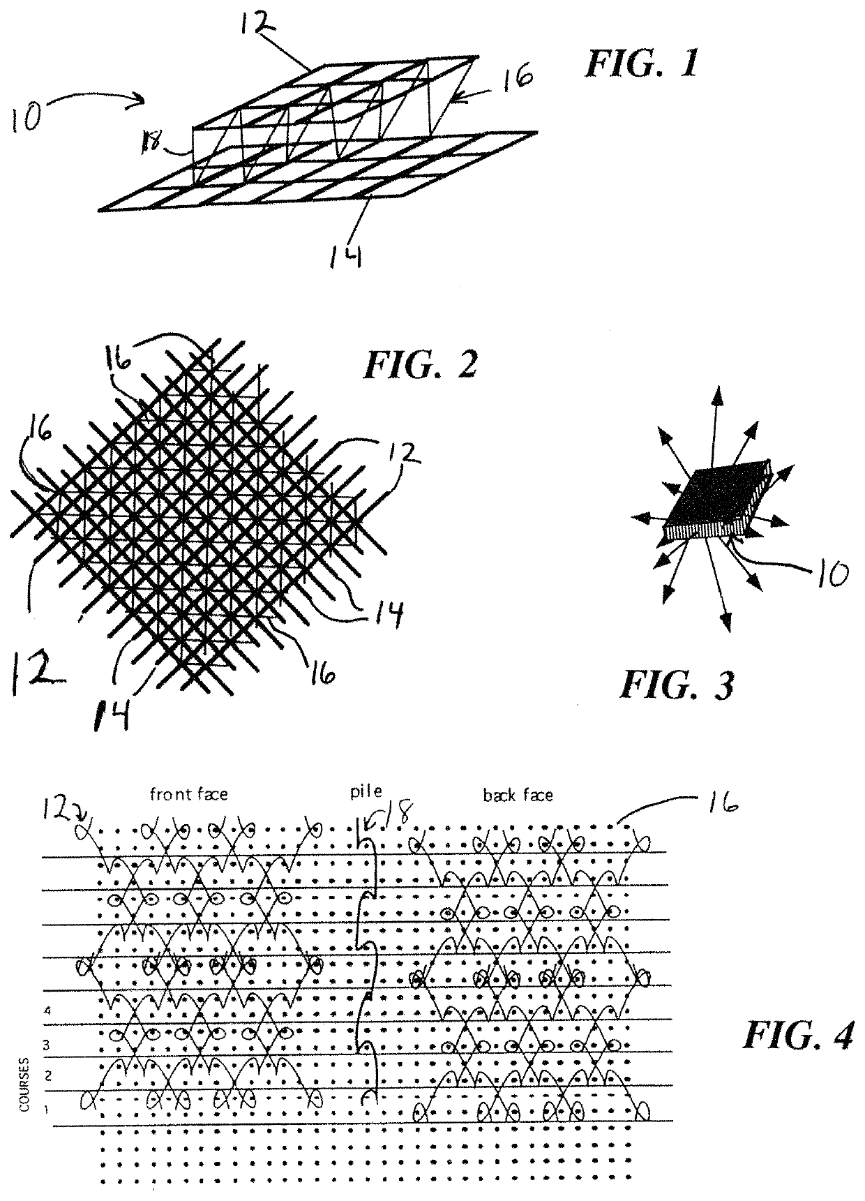
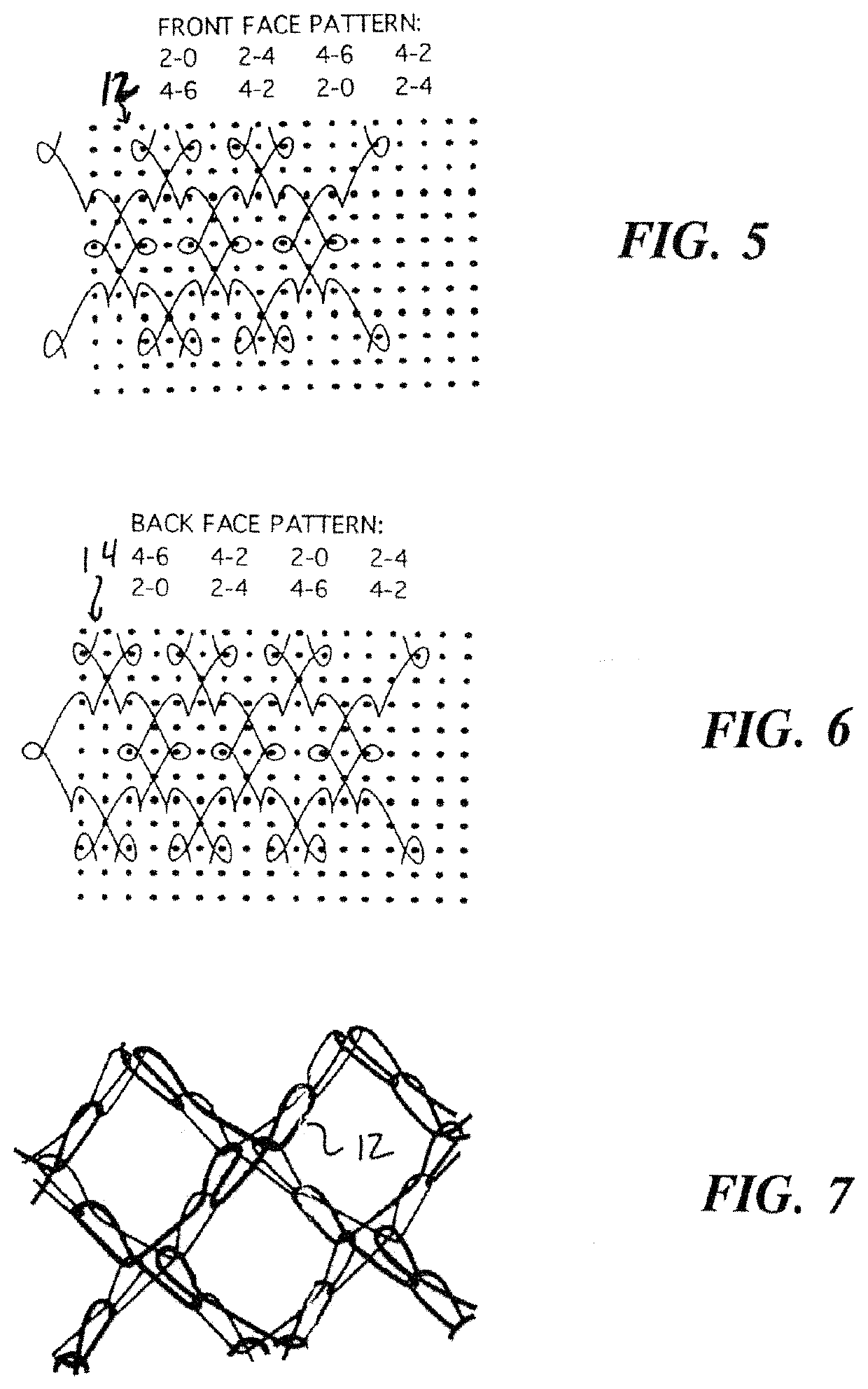
lass="d_n">[0043]In FIG. 1 a camouflaging textile 10 according to the invention is depicted. The textile 10 is a fabric material relying primarily on its geometry for multi-spectral electromagnetic radiation camouflaging effects. The textile fabric 10 including an upper generally planar sheet 12 formed of a fabric that can be knit, woven or formed of bonded fibers and a second, lower generally planar sheet 14 of selected fabric. Preferably, the fabric is woven or knit. For reference orientation purposes herein, upper sheet refers to that sheet subject to exposure and lower sheet refers to that face of the textile closest to the underlying, concealed area / objects.

[0044]The upper sheet 12 and lower sheet 14 are substantially parallel and are connected to each other by a third interposed layer 16 formed from an intertwined yarn / pile 18 which possess adequate stiffness to maintain a substantially constant spacing between the first and second sheet. The pile yarn 18 serves to preserve th...


PUM

PropertyMeasurementUnit
electromagnetic detection resistanceaaaaaaaaaa
optical characteristicsaaaaaaaaaa
dimensionsaaaaaaaaaa

Abstract

An easily handled, lightweight, three-dimensional camouflage material relying on an outer fabric layer and an inner fabric layer separated by an intermediate pile for effective multi-spectral, electromagnetic detection suppression in the visual, near infrared, thermal infrared, microwave, and radar wavebands is provided herein.

Description

TECHNICAL FIELD[0001]The present invention is directed to camouflaging material and, particularly, textile fabric composed of spaced multiple offset layers for improving electromagnetic detection resistance over multiple electromagnetic bands.BACKGROUND OF THE INVENTION[0002]The art of camouflaging fabrics is well established. Many of such fabrics have been devised to defeat detection of infrared and radar sensors.[0003]However, technology has become increasingly sophisticated where it can detect both electromagnetic emission and reflection from a site. Consequently, to defeat detection, camouflage needs to conceal objects from a variety of sensors tuned to any number of visual, near infrared, thermal, and radar wavebands.[0004]The oldest form of camouflage is visual—colored and / or patterned by dying, printing, or garnishing with appropriate materials. The pattern and coloration are chosen to blend with the environment in which it is to be used (woodland, grassland, desert, arctic, ...

Claims


Application Information

Patent Timeline
Patent Type & Authority Patents(United States)
IPC IPC(8): D04B21/20B32B7/027B32B7/05B32B5/02B32B5/26D03D1/00
CPCB32B5/26B32B5/026B32B7/027B32B7/05D04B21/20B32B2459/00B32B5/12B32B2250/03B32B2250/20B32B2262/0261B32B2262/0276B32B2262/106B32B2307/208B32B2307/212B32B2307/718D04B21/12D10B2403/021D10B2507/00
Inventor COX, PHILIP R.
Owner TELEDYNE BROWN ENG A DIV OF TELEDYNE
Learn More