
Stripe based self-gating for retiming pipelines

a self-gating and pipeline technology, applied in the field of stripe-based self-gating for retiming pipelines, can solve the problems of difficult design of complex designs and less efficien

Active Publication Date: 2021-02-09
ADVANCED MICRO DEVICES INC
View PDF13 Cites 0 Cited by
  • Summary
  • Abstract
  • Description
  • Claims
  • Application Information

AI Technical Summary

Benefits of technology

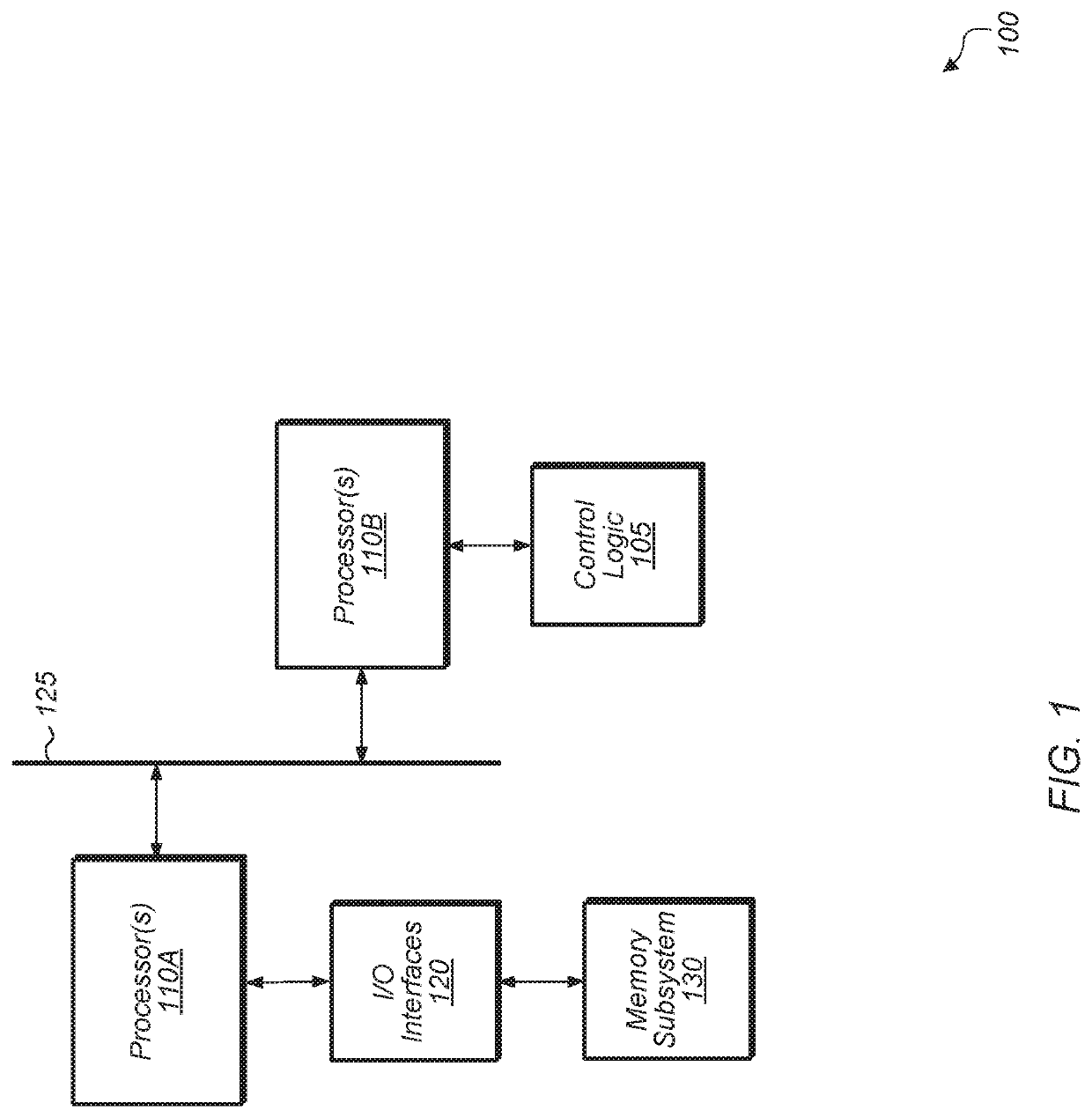
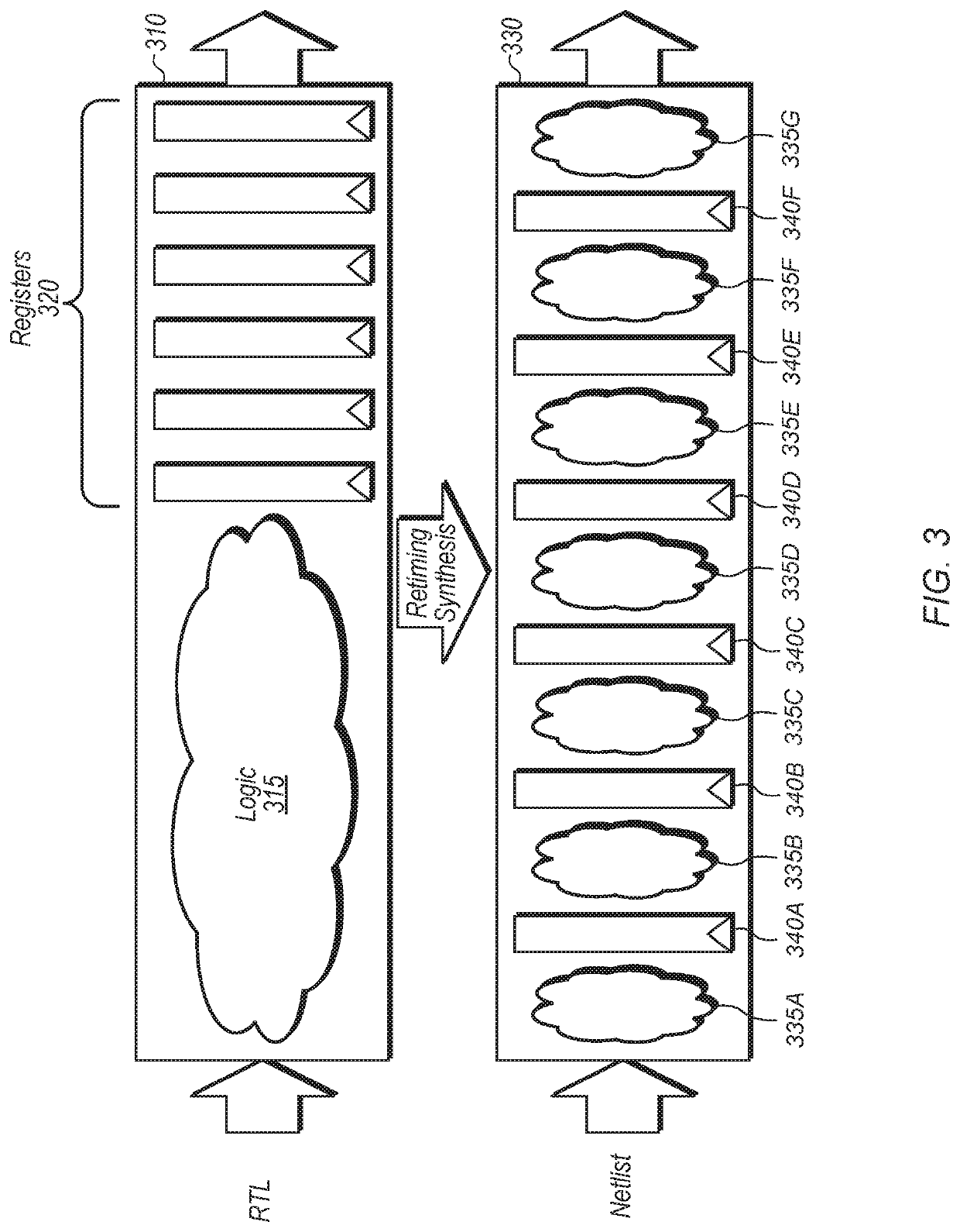
The patent describes a method for optimizing the power consumption of a circuit design by using stripe-based self-gating and change detect signals for retiming pipelines. The method involves generating a netlist representation of the circuit design and analyzing it to partition the circuit design into stripes, with each stripe being optimized to reduce power consumption. The stripes include a plurality of register stages, and self-gating circuitry is added to the first register stage of a stripe to reduce power consumption without requiring self-gating circuitry for the subsequent stages of the stripe. The method also includes generating a change detect signal from the self-gating signals of the first register stage, which is used as a clock enable signal for the registers of the subsequent stages. The use of self-gating circuitry and change detect signals allows for efficient power consumption without sacrificing performance.

Problems solved by technology

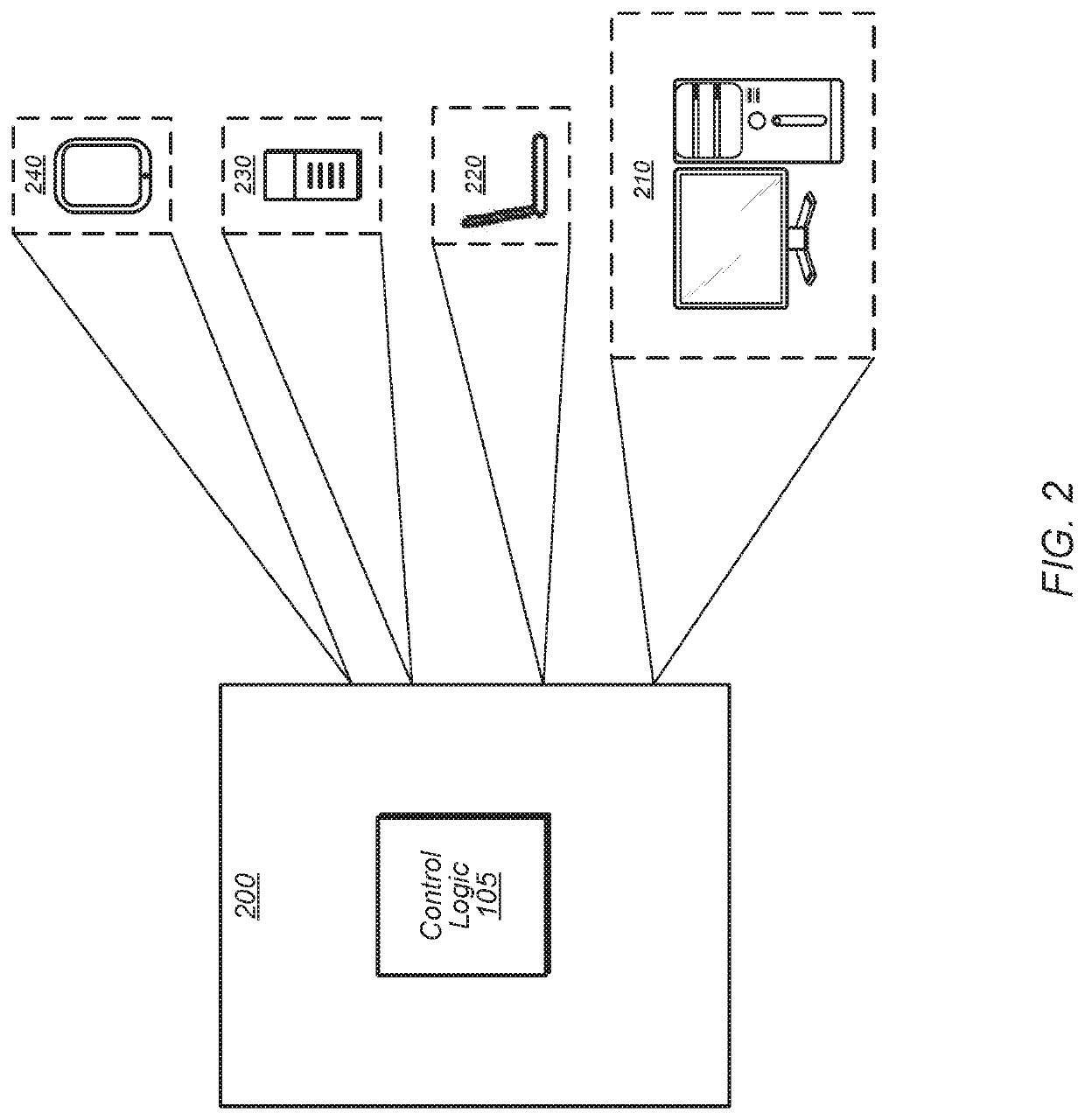
Computing systems often include control logic to perform customized operations that are infeasible or would be less efficient if performed by a main processor.
Complex designs are difficult to design by manually coding each pipeline stage.
But in a large retiming pipeline, each stage only has one clock gating cell to control many registers and not all registers will toggle at the same clock cycle.

Method used


Image

  • Stripe based self-gating for retiming pipelines
  • Stripe based self-gating for retiming pipelines
  • Stripe based self-gating for retiming pipelines

Examples


Embodiment Construction

[0013]In the following description, numerous specific details are set forth to provide a thorough understanding of the methods and mechanisms presented herein. However, one having ordinary skill in the art should recognize that the various implementations may be practiced without these specific details. In some instances, well-known structures, components, signals, computer program instructions, and techniques have not been shown in detail to avoid obscuring the approaches described herein. It will be appreciated that for simplicity and clarity of illustration, elements shown in the figures have not necessarily been drawn to scale. For example, the dimensions of some of the elements may be exaggerated relative to other elements.

[0014]Systems, apparatuses, and methods for stripe-based self-gating and change detect signal propagation for retiming pipelines are disclosed herein. In one implementation, a circuit includes one or more stripes, with each stripe including a plurality of sta...


PUM


Abstract

Systems, apparatuses, and methods for implementing stripe-based self-gating and change detect signal propagation for retiming pipelines are disclosed. A circuit includes one or more stripes, with each stripe including a plurality of stages of registers, with each stage only receiving input signals from the preceding stage. For a given stripe, the first stage of registers are self-gated to reduce power consumption by only clocking a group of registers when any of their input signals change. The self-gating signals of the first stage of registers are combined together to create a change detect signal which is passed through a register and provided to a second stage of registers as a clock-enable signal. Accordingly, the second stage registers are only clocked when the change detect signal indicates a change will be forwarded from the first stage. This reduces power consumption for the second stage without causing the area increase associated with self-gating circuitry.

Description

PRIORITY INFORMATION[0001]This application claims benefit of priority to Chinese Application No. 201910467712.7, entitled “STRIPE BASED SELF-GATING FOR RETIMING PIPELINES”, filed May 31, 2019, the entirety of which is incorporated herein by reference in its entirety.BACKGROUNDDescription of the Related Art[0002]Computing systems often include control logic to perform customized operations that are infeasible or would be less efficient if performed by a main processor. One type of a device used for implementing control logic is an application specific integrated circuit (ASIC). For high frequency digital designs, pipelining is typically performed for the logic blocks of an ASIC design. Complex designs are difficult to design by manually coding each pipeline stage. Retiming is one technique for quickly and efficiently designing a complex pipeline. For low power purposes, clock gating can be implemented for each stage of retimed pipeline. But in a large retiming pipeline, each stage on...

Claims


Application Information

Patent Timeline
IPC IPC(8): H03K19/00G11C19/28G11C19/38
CPCH03K19/0016G11C19/287G11C19/38Y02D10/00H03K19/17736
Inventor MENG, QING
Owner ADVANCED MICRO DEVICES INC
Learn More