Multi-function fuel injector for internal combustion engines and method

a fuel injector and multi-functional technology, applied in the direction of liquid fuel feeders, machines/engines, mechanical apparatus, etc., can solve the problems of limiting the overall market potential of the engine, not allowing for any useful range of variability, and reducing the top end performance, etc., to achieve rapid oem production, increase or decrease the amplitude and/or angle, the effect of low cos

Active Publication Date: 2021-02-16
XCENTRICK INNOVATIONS LTD
View PDF14 Cites 0 Cited by
  • Summary
  • Abstract
  • Description
  • Claims
  • Application Information

AI Technical Summary

Benefits of technology

[0007]Such systems generally allow for ease of removal and installation of the port fuel injectors within and onto the top of the induction conduit or intake manifold by means of a mounting sub-port therein. Such systems generally allow for a significant range of free angled rotation of the fuel injector along its center longitudinal axis in the fully seated and installed position without impacting its performance or causing leaks or any other negative issue. By attaching a an airflow diverting blade like structure to the intra-port tip end of the fuel injector it is possible to take advantage of the typical fuel injector's externally selectively variable rotational angle range of motion to allow for ease post install of manual selection of the angle of the intra-port blade like structure and precisely and incrementally increase or decrease the amplitude and / or angle and / or direction of the air & fuel flow diversion and fuel swirl desired for each individual cylinder therein. These factors make the invention very well suited for very low cost and rapid OEM production and / or the aftermarket, but do not preclude other more complex and / or fixed adaptation of its novel combined functions. Post install externally visible indexing marks, as part of the adapted blade like flow diversion device OR as added to the OEM fuel injector itself, allows for the intra-port adjustable airflow diversion device to be precisely indexed relative to its coaxial engagement with the fuel injector itself and / or relative to the longitudinal induction conduit flow direction, in order to optimize performance and / or fuel efficiency with ease.
[0008]Further the opportunity to improve the fuel delivery location and combustion efficient condition through vapor-phasing is created. This is accomplished Through the addition of the carburetor like barrel and venturi arrangement which when combined with typical port fuel injection creates a Hybrid Fuel Injection (HFI) system. With this system it is possible to create the venturi effect without necessarily reproducing the typical carburetor like ID profile. HFI is capable of maximizing the potential of both systems simultaneously with a simple low cost device that has no moving parts and is self cleaning making it zero (0) maintenance and zero (0) service required for beyond the life of the engine. Early indications from real world application is that HFI may keep an engine internally cleaner than even port fuel injection which is far superior to Direct Injection (DI). HFI can provide much of the same benefits of DI without all the cost, complexity, safety and maintenance drawbacks.

Problems solved by technology

The goal is to find the perfect balance between the amplitude and / or angle of swirl generated and a reduction in the high end airflow dimension which results in reduced top end performance.
These devices are designed to allow for on the fly mass airflow directional variability, but, are very complicated and costly to implement and produce greatly limiting their overall market potential.
Further, in light of the fundamentally antithetical goals, Klaski actually seeks to keep mass air flow diversion to an absolute minimum and not allow for any useful range of variability for generating swirl or any other purpose.
Further, the Klaski device is not well suited for the aftermarket or aftermarket retro-fit as it requires a specially designed fuel injector nozzle not normally used in OEM fuel injectors.

Method used


Image

  • Multi-function fuel injector for internal combustion engines and method
  • Multi-function fuel injector for internal combustion engines and method
  • Multi-function fuel injector for internal combustion engines and method

Examples


Embodiment Construction

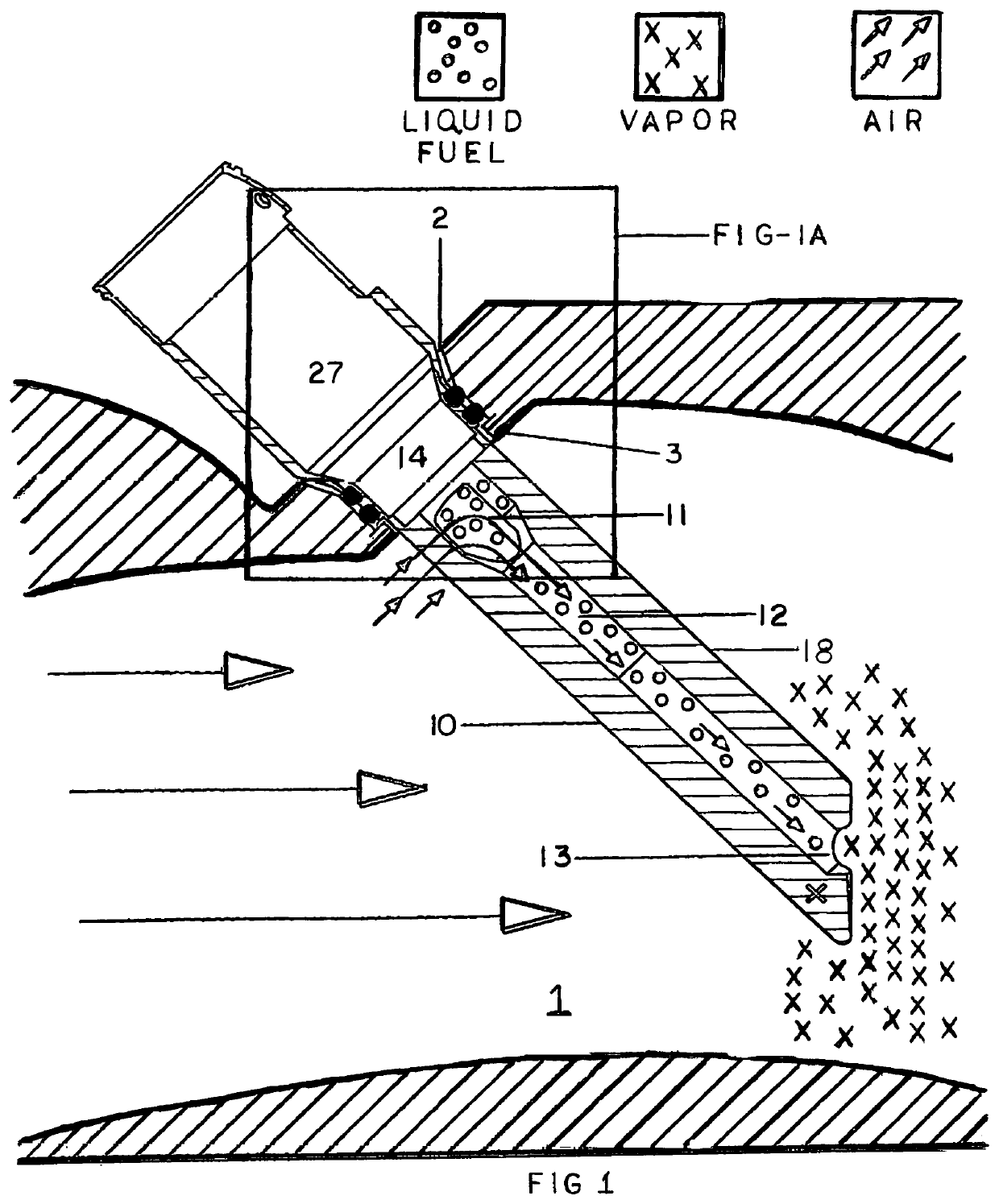
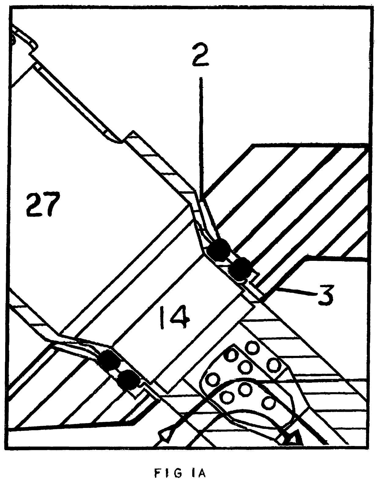
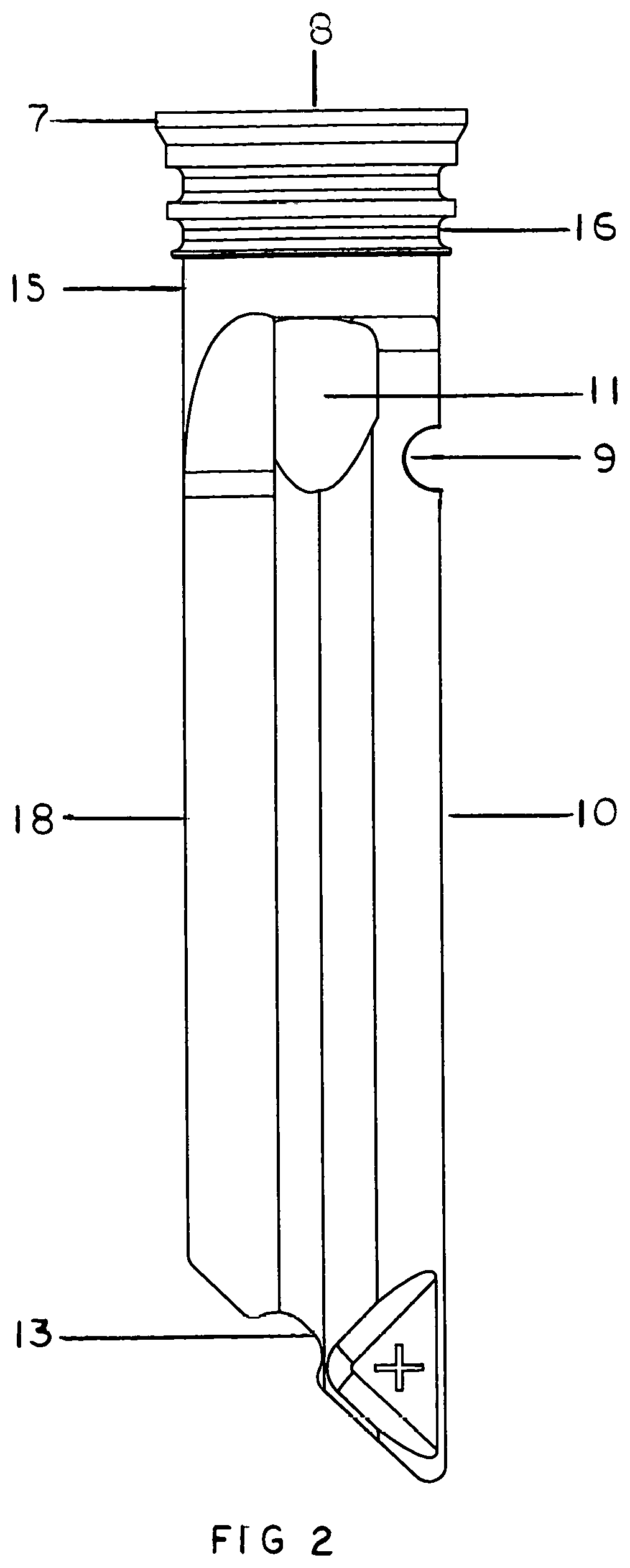
[0015]The basic preferred structures for the Intra-port mass air OR mass air & fuel flow diversion and vapor-phasing devices includes elements that are selected or excluded and mixed and matched to form several useful versions of the fuel injection system disclosed herein which is not necessarily limited to and include:[0016]1. A mounting collar (FIGS. 1 & 2 No. 13&14),[0017]2. seal landings (FIG. 2-4 No. 16),[0018]3. a security retention flange (FIG. 2 No. 17),[0019]4. an extended blade like structure (FIG. 5 No. 17)[0020]5. an internal air and fuel mixing junction (FIG. 1-3 No. 11),[0021]6. an internal hollow tubular venturi effect generating barrel (FIGS. 1 & 5 No. 12), AND,[0022]7. a distribution nozzle (FIG. 1-3 No. 13).

[0023]The preferred “extended blade like structure” defined as a piece of solid material having a leading and a trailing edge (FIGS. 1-3 & 5 No. 10&18) connected on at least one (1) side by flat, straight, angled and / or curved surfaces the total linear combined ...


PUM


Abstract

In the preferred embodiments an air flow diverting blade is integral to a base that doubles as a collar designed to co-axially attach to the nozzle tip end of a typical port fuel injector for internal combustion engines.Upon simple manual manipulation of the set rotational angle of the typically externally exposed portion of the port fuel injector along its longitudinal axis, as typical modern port injection systems allow after installation, the angle of the intra-port flow diverting blade can be selectively varied to either straighten existing swirl and increase top end flow, or, introduce lateral directional swirl to whatever angle and intensity in either direction is desired. The functional use of a typical port fuel injector is thereby elevated to a multifunction of tunable fuel and air flow control at the point of induction into a combustion chamber without any modification to existing engine designs or their engine management control systems employed therefore. The flow diverting blade can be configured to divert flow around the intake valve stem, guide and guide boss in such a manner to optimize the overall flow dimension of the induction system of a typical internal combustion engine. The flow diverting blade also provides an effective means by which the proximity and angle of fuel injection, relative to the combustion chamber, can be altered and improved as desired. The flow diverting blade also provides an effective means by which a modest increase in effective fuel injector nozzle pressure and fuel vaporization can be realized.

Description

BACKGROUND[0001]The generation of a lateral directional swirl condition from the mass airflow stream within the induction conduit (or main port) of the typical Internal combustion (IC) engine generated during its intake cycle has long been recognized as a means to enhance certain desirable performance aspects therein. The goal is to find the perfect balance between the amplitude and / or angle of swirl generated and a reduction in the high end airflow dimension which results in reduced top end performance. Further, the optimal preferred lateral direction of the swirl, from either the left or the right, varies with different IC engine configurations. Vapor-phasing liquid fuel independent of excessive waste heat has also been shown to provide enhanced overall engine efficiency and environmental compatibility. Further, in port fuel injected engines, the location of the final fuel distribution point as well as the angle relative to the longitudinal center axis of a port fuel injector has ...

Claims


Application Information

Patent Timeline
Patent Type & Authority Patents(United States)
IPC IPC(8): F02M61/16F02M61/18F02M69/04F02M51/06F02M61/14
CPCF02M61/162F02M51/061F02M61/145F02M61/18F02M61/1813F02M69/047
Inventor HUFF, REGGIE DWAYNE
Owner XCENTRICK INNOVATIONS LTD
Why Eureka
Try Eureka