Dryer and method of drying

a technology of dryer and dryer, which is applied in the direction of drying, heating apparatus, lighting and heating equipment, etc., can solve the problems of contaminating products, significant risk of burning products, and efficacy of such a prior art dryer

Active Publication Date: 2021-02-23
SANOVO BIOSECURITY AS
View PDF43 Cites 3 Cited by
  • Summary
  • Abstract
  • Description
  • Claims
  • Application Information

AI Technical Summary

Benefits of technology

[0019]Thereby efficacy in terms of the mass of condensate per volume unit that can be extracted from wet or humid items subject to drying in the dryer chamber is increased when compared to a prior art dryer. Further, it is thereby possible to dry wet or humid items at lower temperatures such as at temperatures below 40-50 degrees Celsius e.g. below about 38 degrees Celsius or below about 40 degrees Celsius.
[0024]A compressor is a mechanical device that increases the pressure of a gas, which is compressible, supplied via an inlet to the compressor by significantly reducing its volume at an outlet of the compressor.
[0026]As for the axial flow compressor and other types of compressors it should be mentioned that so-called ‘stators’ help the axial compressor keep the air flowing and properly pressurized. Reciprocating and piston compressors increase the pressure of the incoming gas by reducing its volume by means of a displacing component. Rotary screw type compressors, at least in some embodiments, have rotors that interact to compress the gas continuously.
[0037]Especially, when the gas discharge takes place inside the dryer chamber an improved gas flow inside the dryer chamber and across the wet or humid items may be observed compared to conventional forced circulation of a gas such as air.
[0041]Thereby the discharger exit emits the high intensity sound waves as output from the sound generator and at the same time provide a supply of gas to the drying chamber. High intensity sound waves may have the effect of disrupting a boundary sub-layer surrounding the wet or humid items subject to drying and thereby increase the rate of drying. Drying is conventionally prolonged by a thin protective layer of air or another gas very closely surrounding the items. Such a thin protective layer of air or another gas very closely surrounding the items is also denoted a boundary sub-layer. It has been found that disruption of this boundary sub-laminar layer by high intensity sound pressures improves the rate of drying the wet or humid items. Disruption of this boundary sub-laminar layer by high intensity sound pressures at frequencies above 10 KHz especially improves the rate of drying the wet or humid items.
[0059]Thereby, the mass of condensate that can be drained by means of the separator is improved. This improvement is especially distinct at relatively low temperatures of the compressed gas such as at temperatures below 40-50 degrees Celsius. This effect may also be seen from FIG. 3, cf. the transition towards lower temperature from operation point 302 to operation point 303. For a temperature drop of 25 degrees Celsius, of the compressed gas, the improvement may amount to about 30%.

Problems solved by technology

This type of dryer involves a significant risk of burning the products and different systems are applied in this type of dryer to circumvent this problem.
Further, this type of dryer involves the problem that the pulse gas jet engine produces exhaust gasses that inevitably are conveyed with the hot air when it passes the products.
Thus, there is a risk of contaminating the products by unhealthy exhaust gasses.
However, it remains a problem to improve the efficacy of such a prior art dryer.
However, also for this type of dryer it remains a problem how to improve the efficacy.
High intensity sound waves may have the effect of disrupting a boundary sub-layer surrounding the wet or humid items subject to drying and thereby increase the rate of drying.

Method used


Image

  • Dryer and method of drying
  • Dryer and method of drying
  • Dryer and method of drying

Examples


first embodiment

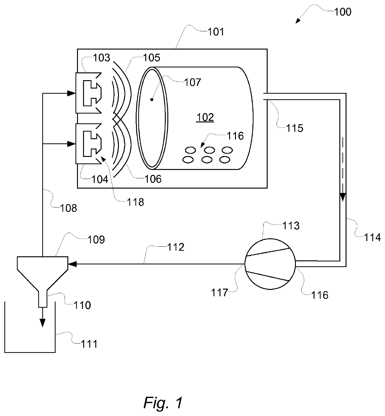
[0097]FIG. 1 shows a dryer. The dryer designated by reference numeral 100, comprises a dryer chamber 101 with a drum 102 with perforations 116 and is coupled to form a closed loop gas-circulating system for circulating gas, such as atmospheric air, through the dryer chamber 101. The gas may comprise additives for treatment of the wet or humid items to be dried.

[0098]The closed loop gas-circulating system recirculates the gas and comprises a compressor 113 coupled to receive return gas from the dryer chamber 101 via a gas outlet 115 of the dryer chamber 101 and via a duct 114 coupled to the outlet 115. The duct is configured to guide a flow of return gas to a compressor intake 116 of the compressor 113 to compress the return gas to provide compressed gas. The compressed gas is provided at a compressor outlet 117 of the compressor 113 Return gas is a relatively humid gas escaping from the dryer chamber via the gas outlet 115 and the duct 114.

[0099]The compressor outlet 117, supplying ...

second embodiment

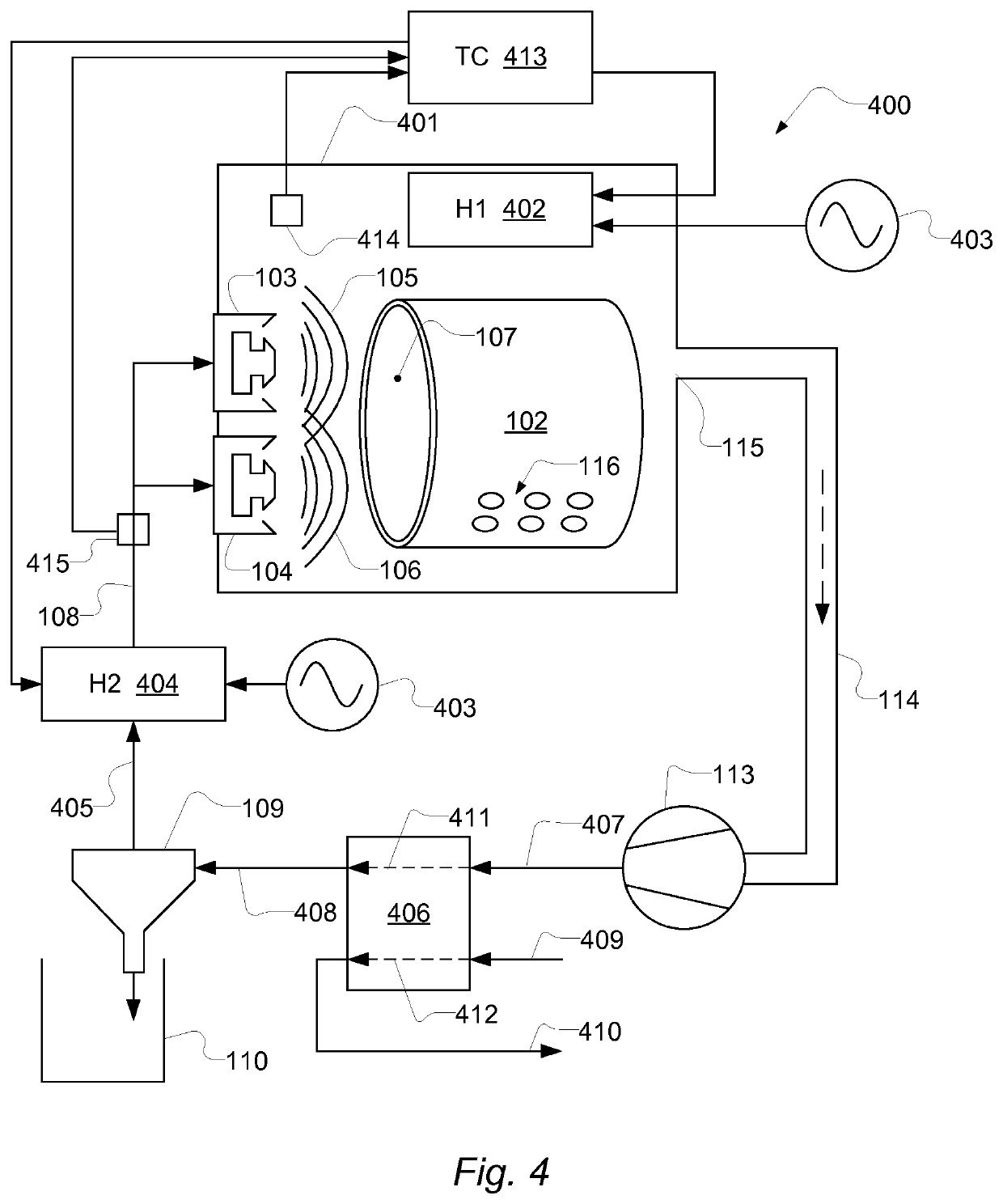
[0106]FIG. 4 shows a dryer. In this embodiment, the dryer 400 comprises a heater H1, 402 installed inside the dryer chamber 401 and being operatively controlled by a temperature controller TC, 413 to maintain a temperature inside the dryer chamber at a set temperature or within a temperature range. The temperature controller 413 is coupled to one or more temperature sensors 414 arranged at the dryer chamber to sense the temperature inside the dryer chamber 401. The heater 402 may be an electric heater e.g. a heater known from conventional tumble dryers such as a heater operated from a mains supply 403 of electrical power. The heater 402 is installed inside the dryer chamber such that heated air or gas can circulate through perforations 116 as it is known in the art.

[0107]The dryer 400 comprises a further heater H2, 404 which is configured to heat compressed gas flowing from the separator 109 to the gas dischargers 103; 104. Compressed gas pipes 108 and 405 deliver the compressed gas...

third embodiment

[0114]FIG. 5 shows a dryer. In this embodiment the dryer is designated by reference numeral 500. Here, the dryer comprises a heat pump 505. The heat pump 505 may an active heat pump comprising a compressor that drives the heat pump circuit. The heat pump comprises a first heat pump gas path 506 sitting in the closed loop gas-circulating system between the compressor 113 and the separator 109 and a second heat pump gas path 507. The second heat pump gas path 507 sits in the closed loop gas-circulating system between the separator 109 and the gas discharger 103;104. The heat pump is configured with a heat pump circuit 508 for extracting heat energy from the first heat pump gas path 506 and delivering heat energy to the second heat pump gas path 507. The heat pump circuit circulates a heat exchanging medium such as a refrigerant.

[0115]In some aspects the heat pump is alternatively coupled to deliver heat energy to a heater H1, 502 installed inside the dryer chamber 501.

[0116]Alternativ...


PUM


Abstract

A dryer (100), comprising a dryer chamber (101) coupled to a closed loop gas-circulating system for circulating gas through the dryer chamber (101); wherein the closed loop gas-circulating system recirculates the gas and comprises: a compressor (113) coupled to receive return gas from the dryer chamber (101) and to compress the return gas to provide compressed gas; a separator (109) sitting in the gas-circulating system for draining condensate from the gas; and a gas discharger (103; 104) coupled to receive compressed gas from the compressor (113) and to discharge the compressed gas through a discharger exit (118). The separator sits in the closed loop gas-circulating system downstream of the compressor to receive compressed gas and upstream of the gas discharger (103;104). Thereby drying efficacy is improved and is advantageous at relatively low drying temperatures such as below 40 degrees Celsius. There is also provided a door for a dryer, a method of operating a dryer and a method of drying, such as a method of drying pharmaceutical substances, compounds, ingredients or products.

Description

CROSS-REFERENCE TO RELATED APPLICATIONS[0001]This application is the U.S. National Phase under 35 U.S.C. § 371 of International Application PCT / EP2017 / 063648, filed Jun. 6, 2017, which claims priority to DK PA201670418, filed Jun. 10, 2016. The disclosures of the above-described applications are hereby incorporated by reference in their entirety.BACKGROUND OF THE INVENTION[0002]Drying is a mass transfer process involving the removal of water or another liquid by evaporation from a solid, semi-solid or liquid item(s) or object(s) to be dried. This process is often used in industry as a production step before packaging of products or in connection with professional or private drying of clothes. A source of heat and an agent to remove the vapour produced by the process are often involved. In bio-products like food, grains, and pharmaceuticals like vaccines, the liquid to be removed is often water.[0003]In the most common case, a gas stream, e.g. a stream of air, applies heat to the obj...

Claims


Application Information

Patent Timeline
Patent Type & Authority Patents(United States)
IPC IPC(8): F26B5/02F26B3/04F26B11/04F26B21/04F26B21/08F26B23/00
CPCF26B5/02F26B3/04F26B11/04F26B21/04F26B21/08F26B21/086F26B23/002F26B23/005Y02P70/10
Inventor KREBS, NIELS
Owner SANOVO BIOSECURITY AS
Why Eureka
Try Eureka