
Method of manufacturing a membrane assembly for EUV lithography, a membrane assembly, a lithographic apparatus, and a device manufacturing method

a technology of euv lithography and manufacturing methods, applied in the field of manufacturing methods of euv lithography membrane assemblies, membrane assemblies, lithographic apparatus, and device manufacturing methods, can solve the problems of manufacturing defects on the substrate, difficult to manufacture the membrane assembly without, and difficult to manufacture the membrane assembly

Active Publication Date: 2021-02-23
ASML NETHERLANDS BV
View PDF19 Cites 0 Cited by
  • Summary
  • Abstract
  • Description
  • Claims
  • Application Information

AI Technical Summary

Benefits of technology

The patent describes a method of manufacturing a membrane assembly for extreme ultraviolet (EUV) lithography. The method involves selectively removing certain parts of the membrane layer and the planar substrate to create a thin membrane that can be easily separated from the substrate. The membrane is held in place by a border region formed from the planar substrate. The method also includes applying a protection layer to the membrane layer and the substrate, and using a removal process to selectively remove the inner region and a portion of the border region. The technical effect of this method is to provide a membrane assembly that is thin and easily separable from the substrate, which is important for the manufacturing process of the membrane assembly.

Problems solved by technology

Contamination on the surface of the patterning device can cause manufacturing defects on the substrate.
It is difficult to manufacture the membrane assembly without the membrane assembly being deformed in the process, for example because of the thinness of the membrane.
It is also difficult to manufacture the membrane assembly without the membrane assembly being damaged or contaminated in the process.
For example, the membrane may be undesirably oxidized or have unwanted contaminant particles deposited on the membrane during the process of manufacturing the membrane assembly.

Method used


Image

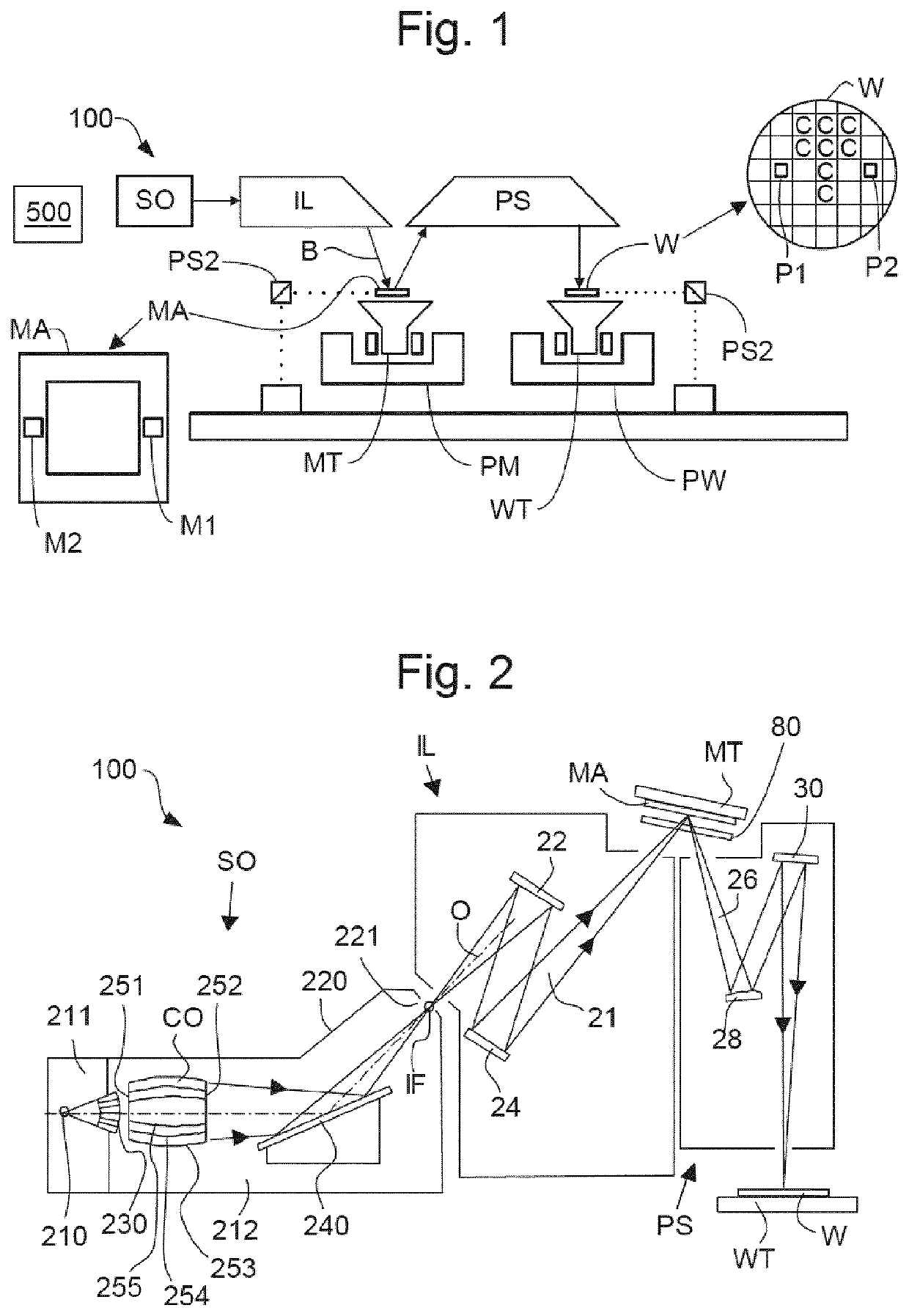
  • Method of manufacturing a membrane assembly for EUV lithography, a membrane assembly, a lithographic apparatus, and a device manufacturing method
  • Method of manufacturing a membrane assembly for EUV lithography, a membrane assembly, a lithographic apparatus, and a device manufacturing method
  • Method of manufacturing a membrane assembly for EUV lithography, a membrane assembly, a lithographic apparatus, and a device manufacturing method

Examples


example processing

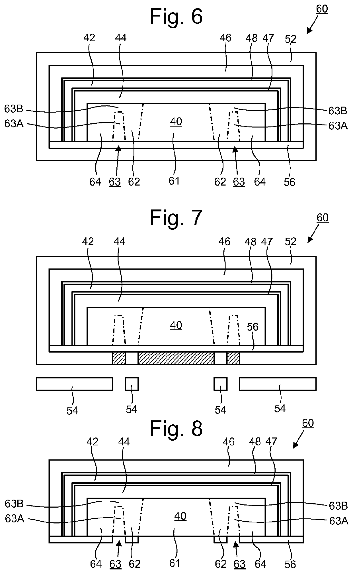
[0101 for manufacturing a membrane assembly to the stage shown in FIG. 10 will now be described in further detail.

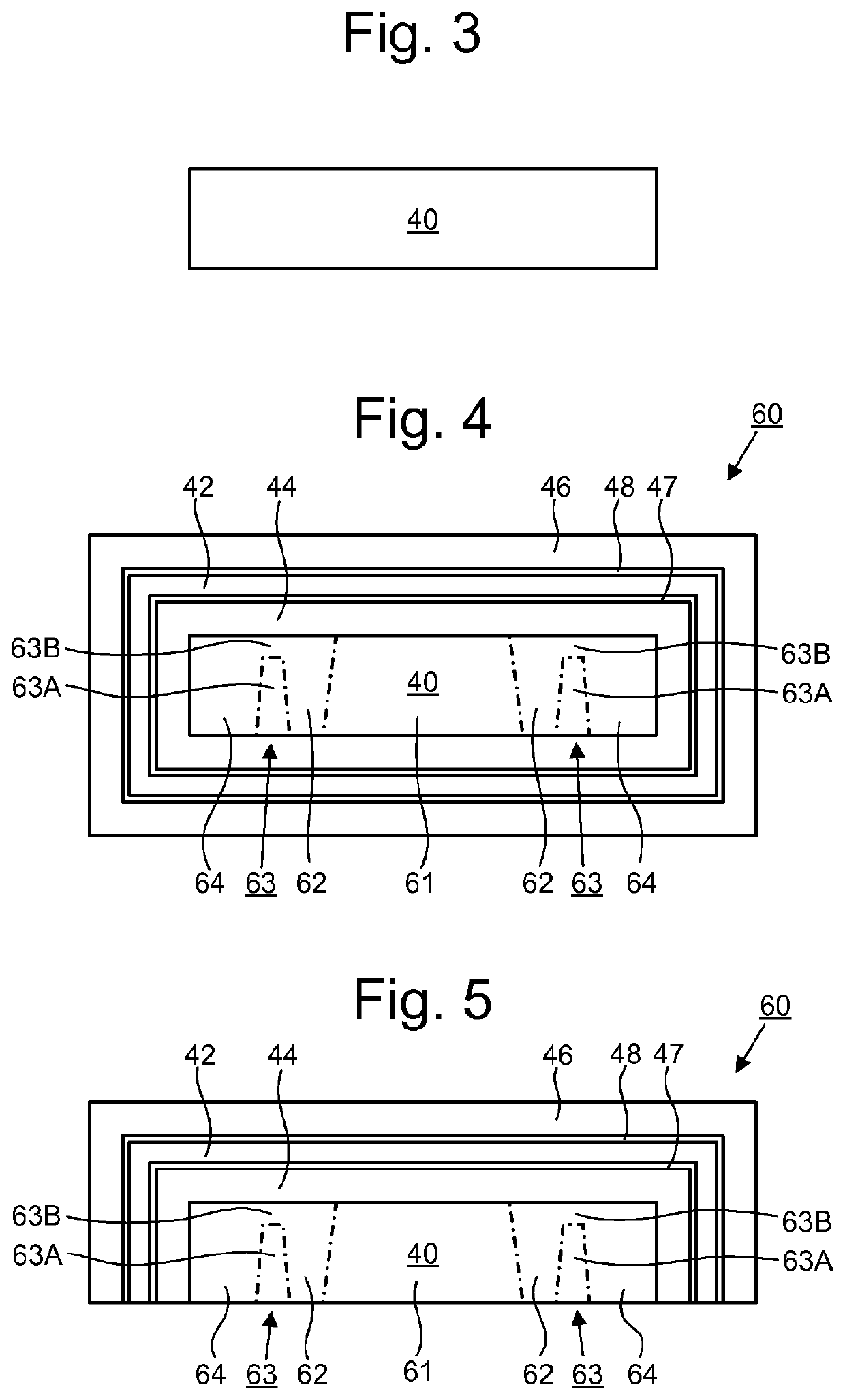
[0102]Initially a planar substrate 40 is provided as shown in FIG. 3.

[0103]The planar substrate 40 is processed to form a stack 60 comprising a sequence of layers on the planar substrate 40 as shown in FIG. 4. The sequence of layers comprises in order from the planar substrate 40 outwards: a lower etch barrier 44, a lower capping film 47, at least one membrane layer 42, an upper capping film 48, and an upper etch barrier 46. Example compositions for the lower etch barrier 44, lower capping film 47, at least one membrane layer 42, upper capping film 48 and upper etch barrier 46 have been disclosed above.

[0104]The stack 60 is processed further to form the stack 60 shown in FIG. 5. In an embodiment the processing comprises multiple consecutive wet and dry etching steps, including top side protection, to etch away the layers on the bottom of the stack 60 up to the planar sub...


PUM

PropertyMeasurementUnit
transparentaaaaaaaaaa
wavelengthaaaaaaaaaa

Abstract

Methods of manufacturing a membrane assembly where, in one arrangement, a stack includes a planar substrate and at least one membrane layer. The planar substrate includes an inner region, a border region around the inner region, a bridge region around the border region and an edge region around the bridge region. The inner region and a first portion of the bridge region are removed. The membrane assembly after removal has: a membrane formed from the at least one membrane layer, a border holding the membrane, the border formed from the border region, an edge section around the border, the edge section formed from the edge region, a bridge between the border and the edge section, the bridge formed from the at least one membrane layer and a second portion of the bridge region. The method further involves separating the edge section from the border by cutting or breaking the bridge.

Description

CROSS-REFERENCE TO RELATED APPLICATIONS[0001]This application is the U.S. national phase entry of PCT patent application no. PCT / EP2016 / 079606, which was filed on Dec. 2, 2016, which claims the benefit of priority of European patent application no. 15201073.2, which was filed on Dec. 18, 2015, and European patent application no. 16171233.6, which was filed on May 25 2016, each of which is incorporated herein in its entirety by reference.FIELD[0002]The present invention relates to a method of manufacturing a membrane assembly for EUV lithography, a membrane assembly, a lithographic apparatus, and a device manufacturing method.BACKGROUND[0003]A lithographic apparatus is a machine that applies a desired pattern onto a substrate, usually onto a target portion of the substrate. A lithographic apparatus can be used, for example, in the manufacture of integrated circuits (ICs). In that instance, a patterning device, which is alternatively referred to as a mask or a reticle, may be used to ...

Claims


Application Information

Patent Timeline
Patent Type & Authority Patents(United States)
IPC IPC(8): G03F1/64G03F1/62
CPCG03F1/64G03F1/62G03F7/70983G03F7/70033G03F7/70916
Inventor JANSSEN, PAULKLOOTWIJK, JOHAN HENDRIKVAN DEN EINDEN, WILHELMUS THEODORUS ANTHONIUS JOHANNESZDRAVKOV, ALEKSANDAR NIKOLOV
Owner ASML NETHERLANDS BV
Learn More