

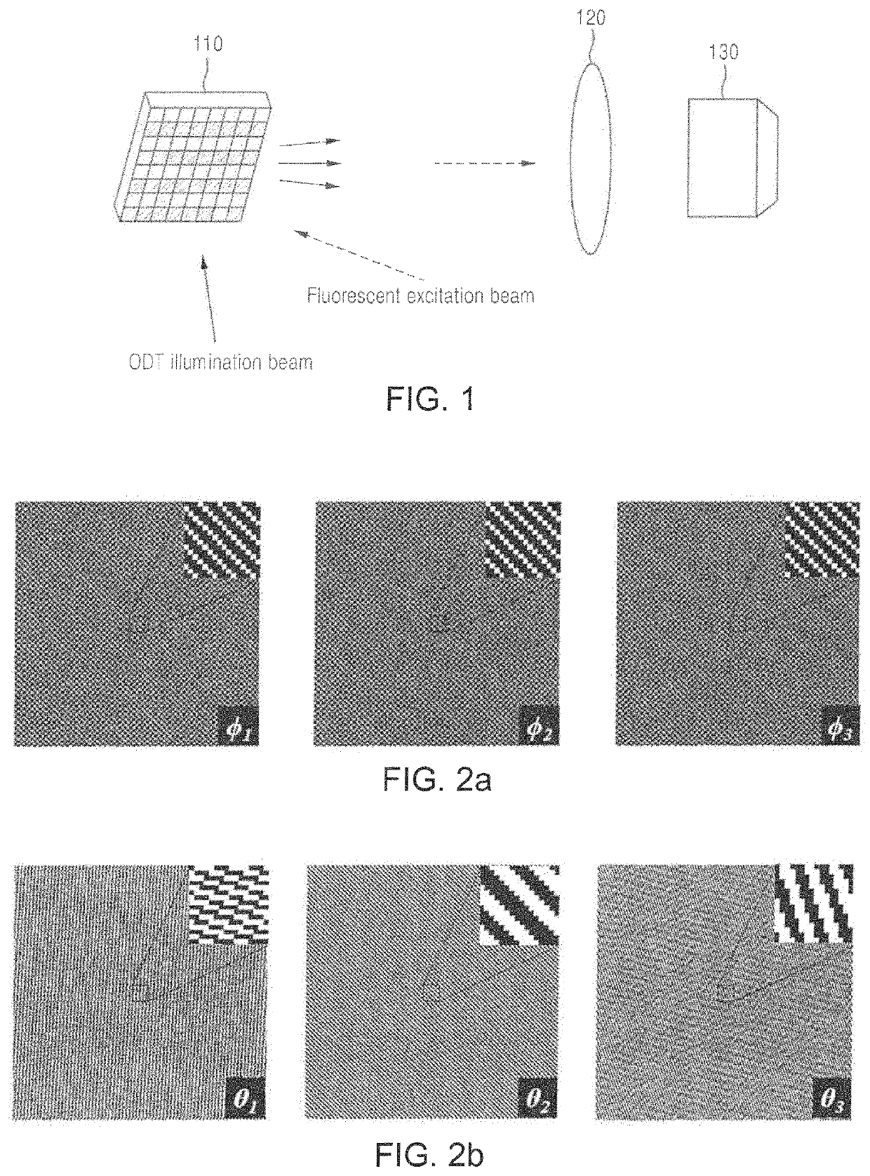
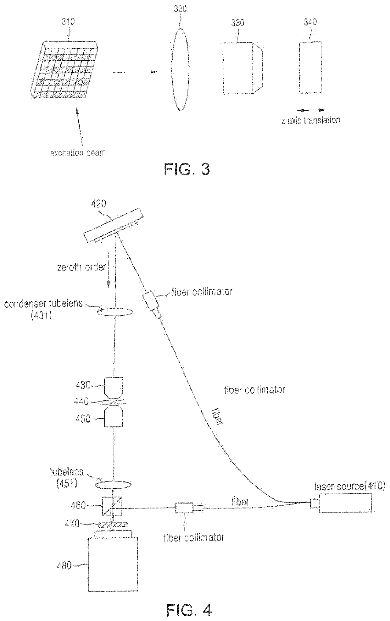
Structured illumination microscopy system using digital micromirror device and time-complex structured illumination, and operation method therefor
a microscopy system and structured illumination technology, applied in the direction of optical elements, fluorescence/phosphorescence, instruments, etc., can solve the problems of inability to make high-speed measurement, vibration and speed limitation, and inability to change the diffraction lattice pattern,
- Summary
- Abstract
- Description
- Claims
- Application Information
AI Technical Summary
Benefits of technology
Problems solved by technology
Method used
Image


Examples
Embodiment Construction
[0195]While a few exemplary embodiments have been shown and described with reference to the accompanying drawings, it will be apparent to those skilled in the art that various modifications and variations can be made from the foregoing descriptions. For example, adequate effects may be achieved even if the foregoing processes and methods are carried out in different order than described above, and / or the aforementioned elements, such as systems, structures, devices, or circuits, are combined or coupled in different forms and modes than as described above or be substituted or switched with other components or equivalents.
[0196]Therefore, other implements, other embodiments, and equivalents to claims are within the scope of the following claims.
PUM
| Property | Measurement | Unit |
|---|---|---|
| phase | aaaaa | aaaaa |
| speed | aaaaa | aaaaa |
| bit depth | aaaaa | aaaaa |
Abstract
Description
Claims
Application Information