Supercharge Your Innovation With Domain-Expert AI Agents!

Exhaust gas purification catalyst body

a technology of exhaust gas and catalyst body, which is applied in the direction of physical/chemical process catalyst, separation process, metal/metal-oxide/metal-hydroxide catalyst, etc., and can solve problems such as air pollution

Active Publication Date: 2021-04-20
CATALER CORP
View PDF32 Cites 1 Cited by
  • Summary
  • Abstract
  • Description
  • Claims
  • Application Information

AI Technical Summary

Benefits of technology

The patent text describes an exhaust gas purification catalyst for internal combustion engines, specifically gasoline engines. The catalyst has a wall flow structure where a catalyst layer is formed in internal pores of a partition wall. By filling small pores in the partition wall with the catalyst layer, the catalyst's performance in collecting particulate matter (PM) decreases. However, by keeping a specific proportion of small pores not filled with the catalyst layer and prioritizing the placement of the catalyst layer in large pores, the catalyst's exhaust gas purification performance is improved without compromising PM collection. This effect is more effective when the temperature of the exhaust gas is relatively high and PM is less likely to deposit in the partition wall.

Problems solved by technology

It is known that the exhaust gas contains particulate matter (PM) containing carbon as a main component, and ash composed of incombustible components in addition to gas components, which cause air pollution.

Method used


Image

  • Exhaust gas purification catalyst body
  • Exhaust gas purification catalyst body
  • Exhaust gas purification catalyst body

Examples


example 1

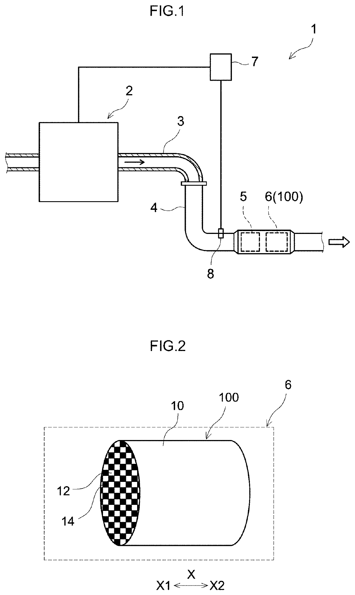
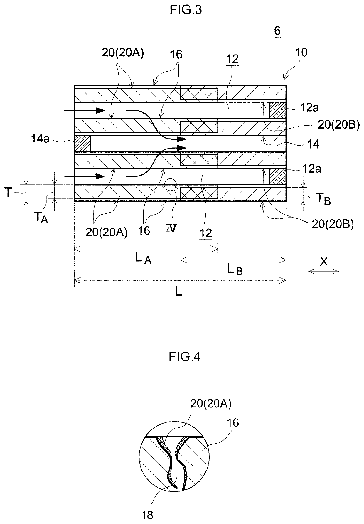
[0079]A Palladium nitrate solution, an alumina powder, a ceria-zirconia composite oxide as a Ce-containing oxide, deionized water, and polycarboxylic acid were mixed to prepare a slurry S1. Next, using a suction coating device, the slurry S1 was applied to an end part (end F) on the exhaust gas inlet side of a cordierite base (wall flow type base shown in FIG. 3: a base volume of 1.3 L, a full length of 114.3 mm) and sucked from the other end R (that is, an end part on the exhaust gas outflow side of the base 10), and thus the slurry was caused to flow into pores in the partition wall. Then, drying and firing were performed and thus a catalyst layer was formed in pores of the partition wall. The viscosity η400 of the slurry S1 at a shear rate of 400 s−1 was 90 mPa·s, and the coating amount of the catalyst layer was 45 g / L. The viscosity η400 of the slurry S1 was adjusted by the amount of polycarboxylic acid. As described above, an exhaust gas purification catalyst body having a cata...

example 2

[0080]A Rhodium nitrate solution, an alumina powder, a ceria-zirconia composite oxide as a Ce-containing oxide, deionized water, and polycarboxylic acid were mixed to prepare a slurry S2. Next, using a suction coating device, the slurry S2 was applied to an end part (end F) on the exhaust gas inlet side of a cordierite base (wall flow-structured base shown in FIG. 3: a base volume of 1.3 L, a full length of 114.3 mm) and sucked from the other end R (that is, an end part on the exhaust gas outflow side of the base 10), and thus the slurry was caused to flow into pores in the partition wall. Then, drying and firing were performed and thus a catalyst layer was formed in pores of the partition wall. The viscosity η400 of the slurry S2 at a shear rate of 400 s−1 was 90 mPa·s, and the coating amount of the catalyst layer was 60 g / L. The viscosity η400 of the slurry S2 was adjusted by the amount of polycarboxylic acid. As described above, an exhaust gas purification catalyst body having a ...

example 3

[0081]An exhaust gas purification catalyst body was produced in the same procedures as in Example 1 except that the coating amount of the catalyst layer per 1 L of the volume of the base was changed to 100 g / L.


PUM

PropertyMeasurementUnit
pore diameteraaaaaaaaaa

Abstract

Provided is an exhaust gas purification catalyst body that can improve exhaust gas purification performance while maintaining favorable PM collection performance. The exhaust gas purification catalyst body includes a base of a wall flow structure having an inlet side cell, an outlet side cell, and porous partition wall, and a catalyst layer that is formed in the partition wall that is in contact with the inlet side cell or the outlet side cell. The catalyst layer is formed in a region of at least 50% of the thickness of the partition wall from a surface of the partition wall, and held on the surface of internal pores in the partition wall in the region.

Description

TECHNICAL FIELD[0001]The present invention relates to an exhaust gas purification catalyst body, and specifically, an exhaust gas purification catalyst body that purifies an exhaust gas discharged from an internal combustion engine such as a gasoline engine.[0002]This application claims the benefit of foreign priority to Japanese Patent Application No. 2017-180851, filed 21 Sep. 2017, the content of which is herein incorporated by reference in its entirety.BACKGROUND ART[0003]In the related art, an exhaust gas purification catalyst for purifying components such as hydrocarbons (HC), carbon monoxide (CO), nitrogen oxides (NOx), and the like contained in exhaust gas is generally provided in an exhaust passage of an internal combustion engine. It is known that the exhaust gas contains particulate matter (PM) containing carbon as a main component, and ash composed of incombustible components in addition to gas components, which cause air pollution. Therefore, in addition to exhaust gas ...

Claims


Application Information

Patent Timeline
Patent Type & Authority Patents(United States)
IPC IPC(8): B01D53/94B01J35/10B01D46/00F01N3/022F01N3/035B01D46/24F01N3/10F01N3/28B01J35/04
CPCB01D53/945B01D46/0027B01D46/2429B01J35/04B01J35/1076F01N3/0222F01N3/035F01N3/101F01N3/2828B01D2046/2437B01D2255/1023B01D2255/2065B01D2255/9155B01D2279/30F01N2330/06F01N2330/36F01N2370/02F01N2510/06B01D53/94B01J23/63F01N3/022F01N3/28B01J37/0215B01J37/038B01D46/24492B01J35/56B01J35/60B01J35/657
Inventor ONOE, RYOTATODA, YOSUKEMIURA, TAKU
Owner CATALER CORP
Features
  • R&D
  • Intellectual Property
  • Life Sciences
  • Materials
  • Tech Scout
  • Unparalleled Data Quality
  • Higher Quality Content
  • 60% Fewer Hallucinations
Learn More