
Coating system for coating a surface of a substrate

a coating system and substrate technology, applied in the direction of film/foil adhesives, machines/engines, final product manufacturing, etc., can solve the problems of affecting the progression of erosion, the density of particles is also influencing the erosion progression, and the underlying structure may be permanently damaged, etc., to achieve efficient, convenient and reliable means

Active Publication Date: 2021-05-04
PATENTCO APS
View PDF15 Cites 0 Cited by
  • Summary
  • Abstract
  • Description
  • Claims
  • Application Information

AI Technical Summary

Benefits of technology

[0033]An example of an application may be a leading edge protection coating on a wind turbine blade. Where the leading edge protection is gradually eroded and thus the performance of the blade is reduced below acceptable limits.
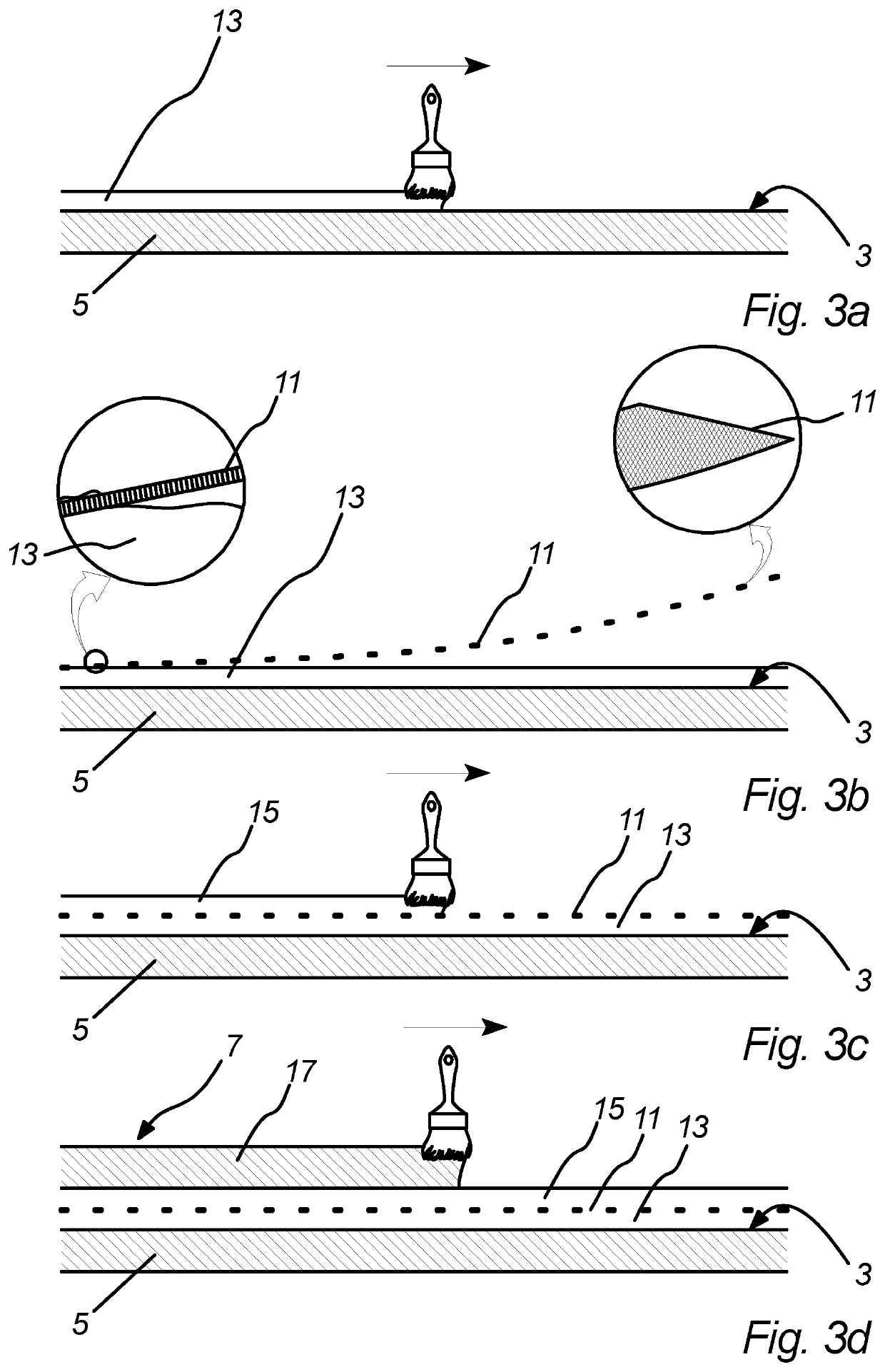
[0100]Thereby is enabled an efficient, convenient and reliable way of applying the coating system of the invention to the substrate before the substrate leaves manufacturing for in-field operation.

Problems solved by technology

Surfaces that are exposed to the elements may be subject to erosion caused by abrasion by particles and water droplets in the air that are present in the environment.
Moreover, the density of particles is also influencing the progression of the erosion.
Should the protective coating be completely removed such that the underlying structure is exposed to the environment said underlying structure may be permanently damaged.
In case of a damaged underlying structure the process of restoring the underlying structure to its original strength and function may be costly if possible at all.
Therefore the erosion becomes more severe with increased span and increased rotational speed of the wind turbine.
As the leading edge erodes the performance of the wind turbine blade deteriorates.
It has been found that even light erosion may lead to a 5% decrease in annual energy production, and heavy erosion may reduce energy production by as much as 25%.
However, in relation to wind turbines located off-shore the challenges with leading edge maintenance are amplified.
Special tools are required to achieve this which increases the cost of the maintenance operation.
The coating is difficult to remove due to its resilience and adherence to the surface.
This is time consuming and therefore requires the wind turbine to be stopped for a relatively long time, during which the wind turbine is out of production.
Therefore an increased downtime reduces the availability of time windows in which the maintenance procedure can be completed.
Therefore, over time, there is a build-up of coating that changes the aero dynamic profile of the coated structure.
This is a major problem in relation to a wind turbine blade, where the aerodynamic shape of especially the leading edge is critical to the performance of the blade.

Method used


Image

  • Coating system for coating a surface of a substrate
  • Coating system for coating a surface of a substrate
  • Coating system for coating a surface of a substrate

Examples


first embodiment

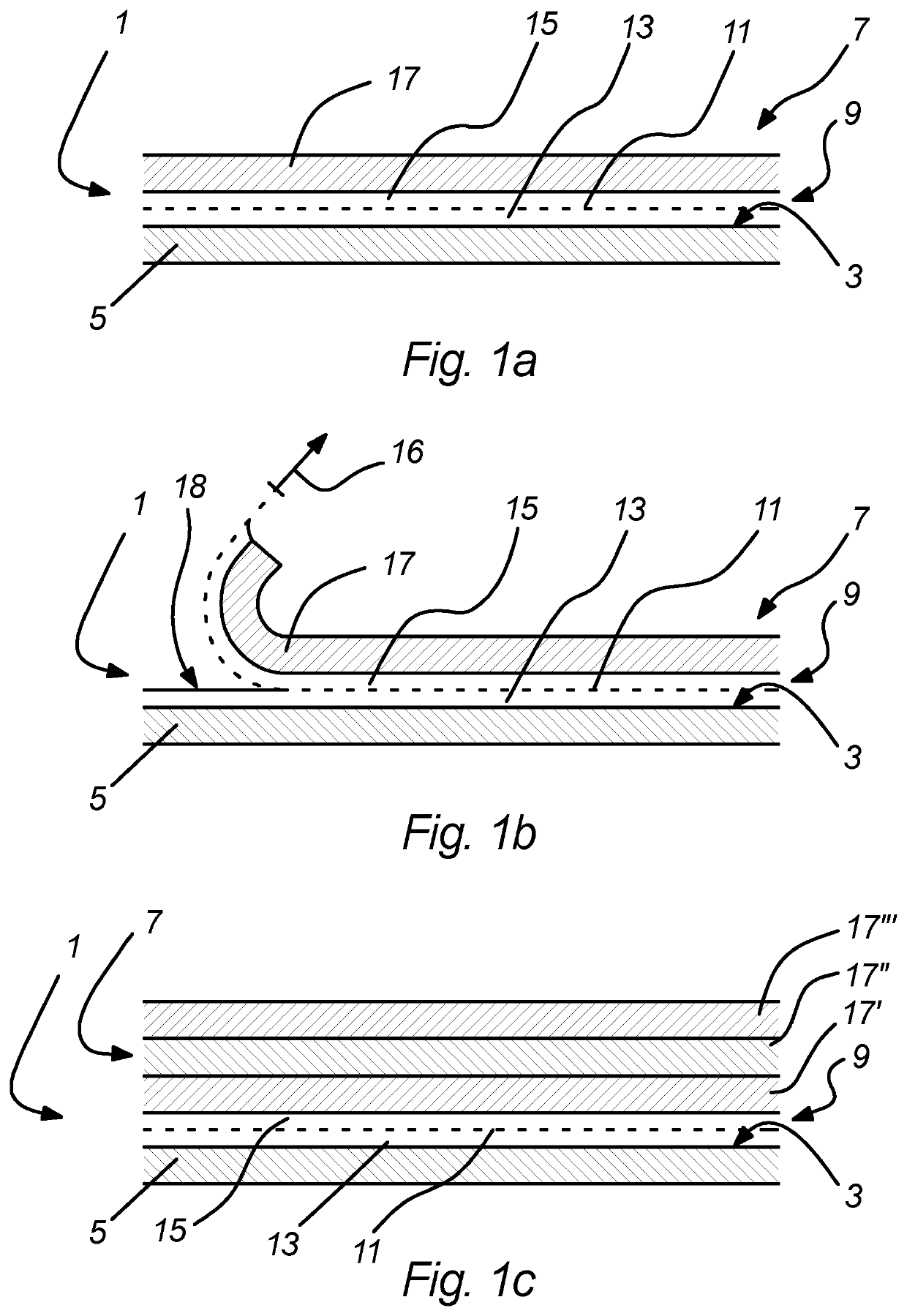
[0121]FIGS. 1a and 1b shows a cross section of a coating system 1 for coating the surface 3 of a substrate 5.

[0122]The coating system 1 comprises a coating 7 and an adhesive layer 9.

[0123]The coating 7 may be any coating that is suitable for a given application. An example of a coating 7 is an erosion resistant material, such as a material with relatively higher resistance to erosion for example by a flow of fluids, than the substrate itself.

[0124]The adhesive layer 9 comprises a carrier 11 and an adhesive. The adhesive layer material is divided by the carrier 11 into a first adhesive layer portion 13 that adheres to the surface 3 of the substrate 5 and a second adhesive layer portion 15 that adheres to the coating 7. Both adhesive layer portions 13, 15 adhere to the carrier 11.

[0125]The first adhesive layer portion 13 comprises a first adhesive layer material and the second adhesive layer portion 15 comprises a second adhesive layer material.

[0126]The first and second adhesive laye...

second embodiment

[0133]FIG. 1c shows a cross section of a coating system 1 according to the invention.

[0134]The second embodiment differs from the first embodiment in that the second embodiment comprises a plurality of coating layers 17′, 17″, 17′″.

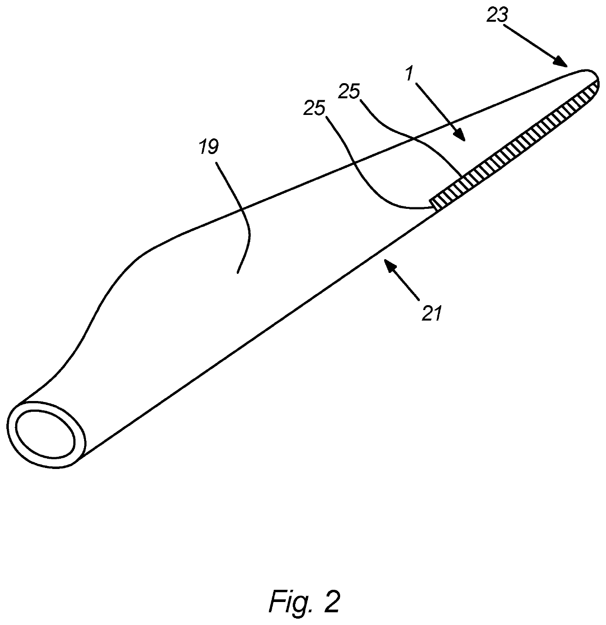
[0135]FIG. 2 shows a wind turbine blade 19 comprising a coating system 1 according to the invention.

[0136]In the embodiment shown the coating system 1 is applied to the leading edge 21 of the wind turbine blade 19, more specifically the part of the leading edge 21 that is closer to the tip 23 of the blade.

[0137]The carrier is not visible on FIG. 2. However, in one embodiment the coating system 1 comprises a single carrier 11.

[0138]Tear strips 25 are embedded at the outline of the carrier 11. When pulling the tear strips 25 the coating 9 is cut and the carrier 11 becomes accessible.

[0139]In one embodiment (Not shown in FIG. 2) the coating system 1 comprises a plurality of discrete carriers 11.

[0140]In all embodiments shown the adhesive can be selected amon...


PUM

PropertyMeasurementUnit
tensile strengthaaaaaaaaaa

Abstract

Coating system (1) for coating a surface (3) of a substrate (5), the coating system (1) comprising; a coating (7), and an adhesive layer (9), that is disposed between the substrate (5) and the coating (7), wherein the adhesive layer (9) comprises a first adhesive layer portion (13) adjacent the substrate (5) and a second adhesive layer portion (15) adjacent the coating (7) and a carrier (11) placed between said first and second adhesive layer portions (13, 5), wherein the first adhesive layer portion (13) is composed of a first adhesive layer material, wherein the second adhesive layer portion (15) is composed of a second adhesive layer material, wherein the first adhesive layer material and the second adhesive layer material is having an adhesive or bond strength to the surface (3) of the substrate (5) and to the coating (7) respectively that exceeds their respective cohesive or tensile strength, wherein the first and second adhesive layer materials and carrier (11) combination is configured for having an adhesive strength that is less than their respective cohesive or tensile strength, wherein the carrier (11) is configured with grab tensile properties such that the carrier (11) in combination with the second adhesive layer portion (15) and the coating (7) will separate from the first adhesive layer portion (13) under the action of a peeling force.

Description

TECHNICAL FIELD[0001]The present invention relates to a coating system for coating a surface of a substrate.[0002]Moreover, the present invention relates to a method of repairing a damaged coating of a coating system on a surface of a substrate.[0003]Additionally, the present invention relates to a method of retrofitting said coating system to the surface of a substrate.[0004]Furthermore, the present invention relates to a substrate comprising said coating system.BACKGROUND[0005]Surfaces that are exposed to the elements may be subject to erosion caused by abrasion by particles and water droplets in the air that are present in the environment. The erosion process is accelerated when the particles are passing the surface at high speed. Moreover, the density of particles is also influencing the progression of the erosion.[0006]This applies to surfaces placed in adverse environments and surfaces placed outside and exposed to the weather as well as submerged surfaces that are exposed to ...

Claims


Application Information

Patent Timeline
Patent Type & Authority Patents(United States)
IPC IPC(8): C09J7/25F01D5/28B32B7/12B32B5/02B32B3/26B32B27/12B32B27/40B32B7/06B32B27/06B32B5/08B32B5/26B32B3/02F03D13/25F03D1/06F03B17/06
CPCC09J7/255B32B3/02B32B3/266B32B5/02B32B5/022B32B5/024B32B5/08B32B5/26B32B7/06B32B7/12B32B27/06B32B27/12B32B27/40F01D5/288F03D1/0675F03D13/25B32B2255/02B32B2255/26B32B2255/28B32B2262/0261B32B2262/0269B32B2262/0276B32B2262/065B32B2262/101B32B2262/106B32B2262/108B32B2262/14B32B2307/748B32B2419/00B32B2603/00B32B2605/18F03B17/061F05B2230/90F05B2280/6011F05D2230/90F05D2300/224F05D2300/30F05D2300/42F05D2300/43F05D2300/611Y02E10/72Y02T50/60Y02E10/727Y02E10/30Y02P70/50
Inventor IBSEN, DITTE HOFMAN
Owner PATENTCO APS
Learn More