Sliding component

a technology of sliding components and components, applied in the direction of engine components, mechanical equipment, coatings, etc., can solve the problems of poor machining properties, high cost, and silicate carbide, and achieve the effects of preventing the deposition of silicate compounds, preventing leakage of sealed fluid, and maintaining the smooth sealing fa

Active Publication Date: 2021-05-18
EAGLE INDS +1
View PDF12 Cites 7 Cited by
  • Summary
  • Abstract
  • Description
  • Claims
  • Application Information

AI Technical Summary

Benefits of technology

[0024](1) By forming the amorphous carbon film whose content of silicon is 1.5 at % or less on at least any one of the sealing faces of the stationary side seal ring and the rotating side seal ring by using the hydrocarbon gas containing no silicon compound, the sealing face of the stationary side seal ring or the rotating side seal ring has a lower affinity with silicate, and it is possible to prevent deposition of a silicate compound contained in the sealed fluid on the sealing face. Thus, it is possible to maintain smoothness of the sealing face and prevent leakage of the sealed fluid.(2) Even in a case where silicon carbide which is a favorable material having a good heat release property and excellent wear resistance as the sliding material of the mechanical seal, etc. is used as the substrate of the stationary side seal ring or the rotating side seal ring, it is possible to prevent deposition of a silicate compound contained in the sealed fluid on the sealing face by the amorphous carbon film whose content of silicon is 1.5 at % or less. Thus, it is possible to maintain smoothness of the sealing face and prevent leakage of the silicate-containing sealed fluid.(3) It is possible to prevent deposition of a silicate compound contained in the sealed fluid by the dynamic pressure generation mechanism formed on at least one of the sealing faces of the stationary side seal ring and the rotating side seal ring with the amorphous carbon film whose content of silicon is 1.5 at % or less. Thus, it is possible to generate dynamic pressure between the sealing faces and make sliding in a low friction and low leakage state without losing functions of the dynamic pressure generation mechanism.

Problems solved by technology

Silicon carbide is a favorable material as the sliding material of the mechanical seal but expensive and poor in a machining property.

Method used


Image

  • Sliding component
  • Sliding component
  • Sliding component

Examples


example 1

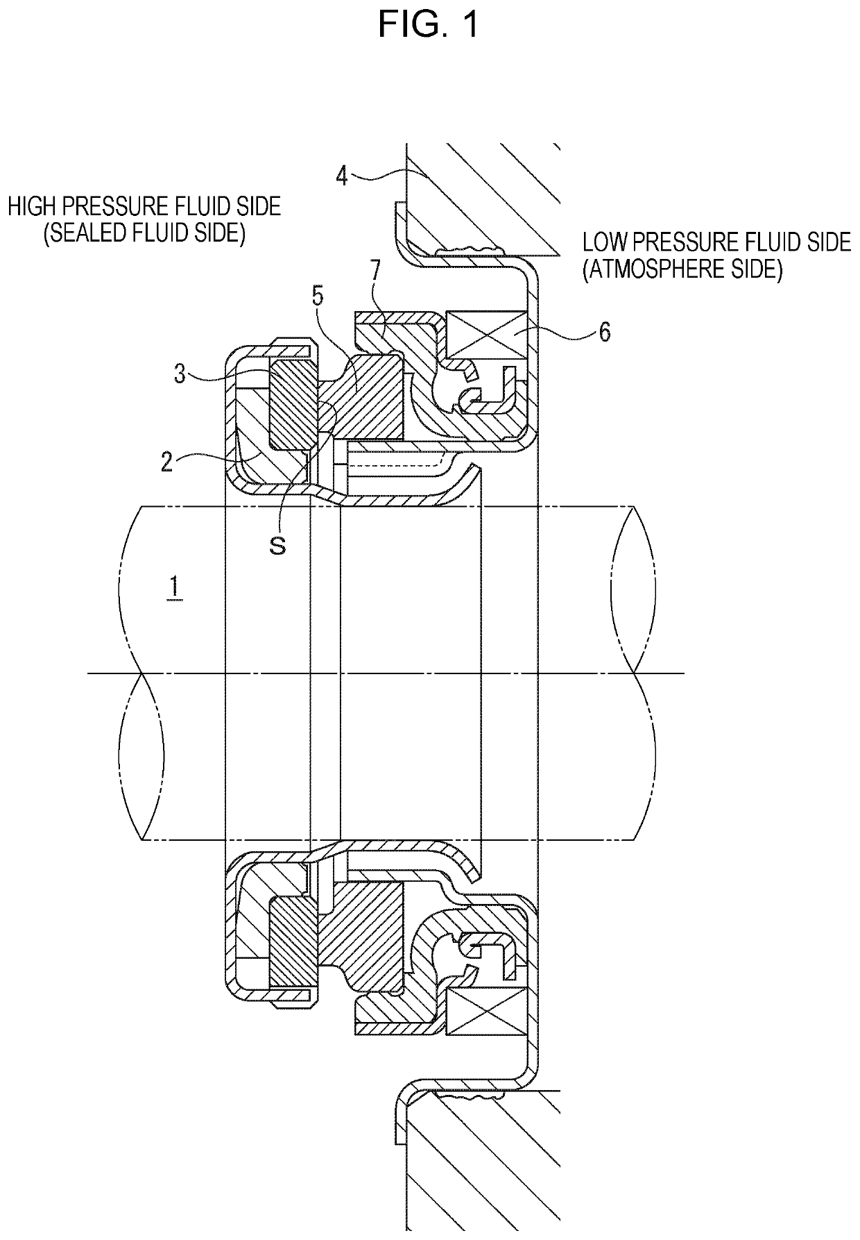
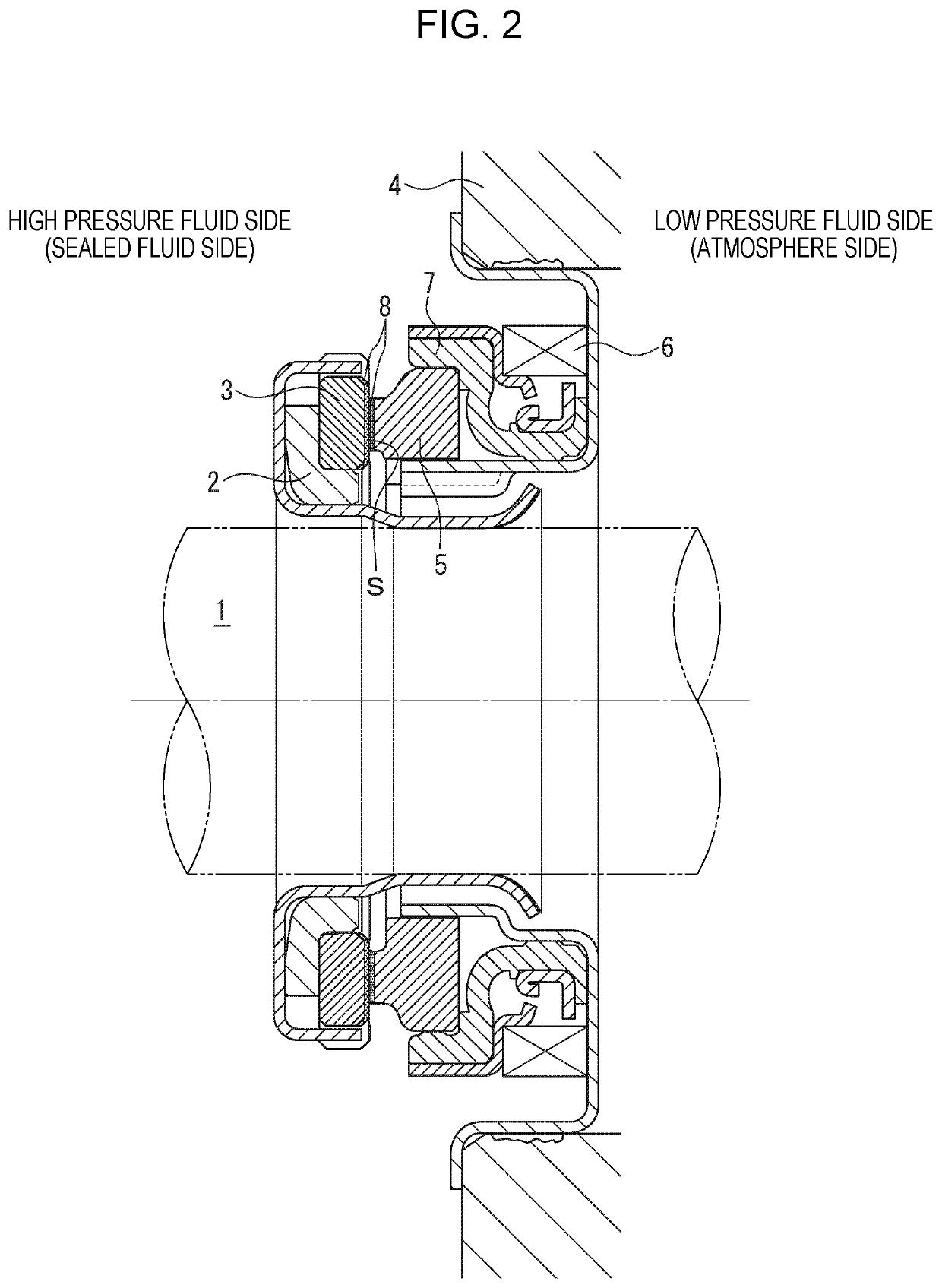
[0054]The sealing faces S of the annular substrates made of silicon carbide formed for the rotating side seal ring 3 and the stationary side seal ring 5 were processed to be smooth by lapping. In a plasma CVD device, by using a hydrocarbon gas containing no silicon compound, an amorphous carbon film having thickness of 150 nm was laminated on the sealing faces S of the substrates of the rotating side seal ring 3 and the stationary side seal ring 5, and a sliding test was conducted under the following sliding test conditions.

[0055]In this case, content of silicon emitted from the substrates made of silicon carbide as outgassing by plasma treatment and contained in the amorphous carbon film was 0.07 at %.

[0056]The content of silicon in the amorphous carbon film was determined by performing narrow measurement on a smooth portion where a dynamic pressure generation groove, etc. are not processed by the X ray photoelectron spectroscopy (XPS) (PHI Quantera SXM by ULVAC-PHI, INCORPORATED.)...

example 2

[0064]In the state of Example 1, the amorphous carbon film was laminated only on the sealing face S of the substrate of the stationary side seal ring 5. A result of the test conducted under the sliding test conditions of Example 1 will be shown in Table 1.

example 3

[0065]In the state of Example 1, by using a hydrocarbon gas containing no silicon compound, an amorphous carbon film whose content of silicon is 0.24 at % and film thickness is 150 nm was laminated on the sealing faces S of the substrates of the rotating side seal ring 3 and the stationary side seal ring 5. A result of the test conducted under the sliding test conditions of Example 1 will be shown in Table 1.


PUM

PropertyMeasurementUnit
thicknessaaaaaaaaaa
widthaaaaaaaaaa
widthaaaaaaaaaa

Abstract

In an exemplary embodiment, a sliding component includes an annular stationary side seal ring 5 fixed to the stationary side and an annular rotating side seal ring 3 to be rotated together with a rotating shaft, in which by relatively rotating opposing sealing faces S of the stationary side seal ring 5 and the rotating side seal ring 3, a silicate-containing sealed fluid present on one side in the radial direction of the relatively rotating sealing faces S is sealed, wherein an amorphous carbon film 8 formed by using a hydrocarbon gas containing no silicon compound is provided on at least any one of the sealing faces S of the stationary side seal ring 5 and the rotating side seal ring 3, and content of silicon of the amorphous carbon film 8 is 1.5 at % or less.

Description

CROSS-REFERENCE TO RELATED APPLICATIONS[0001]This application is the U.S. National Phase under 35 U.S.C. § 371 of International Application PCT / JP2017 / 035394, filed Sep. 29, 2017, which claims priority to Japanese Patent Application No. 2016-202393, filed Oct. 14, 2016. The International Application was published under PCT Article 21(2) in a language other than English.TECHNICAL FIELD[0002]The present invention relates to a sliding component suitable, for example, as a mechanical seal, a bearing, and other sliding units. In particular, the present invention relates to a sliding component such as a seal ring or a bearing that requires reduction of friction by interposing a fluid between sealing faces, and prevention of leakage of the fluid from the sealing faces.BACKGROUND ART[0003]In order to maintain a sealing property in the long term in a mechanical seal serving as an example of a sliding component, contradictory conditions of “sealing” and “lubrication” have to be compatible wit...

Claims


Application Information

Patent Timeline
Patent Type & Authority Patents(United States)
IPC IPC(8): F16J15/3284F16J15/00F16J15/3232
CPCF16J15/3284F16J15/002F16J15/3232C23C16/27F16J15/34F16J15/3412F16J15/3496F16C33/72
Inventor ITADANI, MASATOSHISUNAGAWA, KAZUMASAOKADA, TETSUZOCHIBA, KEIICHIKIRYU, KENJIKIMURA, TADAHIROKOGA, AKIKO
Owner EAGLE INDS
Why Eureka
Try Eureka