Wafer heating and holding mechanism and method for rotary table, and wafer rotating and holding device

a technology of holding mechanism and rotary table, which is applied in the direction of electric/magnetic/electromagnetic heating, photomechanical apparatus, instruments, etc., can solve the problems of unstable etching distribution, poor heating efficiency and low precision, and achieve stable etching.

Active Publication Date: 2021-07-06
MIMASU SEMICON IND CO LTD
View PDF19 Cites 0 Cited by
  • Summary
  • Abstract
  • Description
  • Claims
  • Application Information

AI Technical Summary

Benefits of technology

[0015]According to one embodiment of the present invention, there is provided a remarkable effect of enabling provision of the wafer heating and holding mechanism for a rotary table, the wafer heating method for a rotary table, and the wafer rotating and holding device with which a wafer put on a rotary table can be heated while being rotated stably under a state in which the in-plane temperature distribution of the wafer is maintained. According to the present invention, a wafer is heated directly, and hence the wafer is hardly subjected to external influence and can therefore be etched stably.

Problems solved by technology

Those methods of the related art, however, have poor efficiency and low precision in the heating of the wafer substrate, and consequently tend to invite unstable etching distribution.
Further, stable processing is hindered by the influence of the temperature of a chemical solution, blowing for preventing the chemical solution from running over to the rear side, ventilation for removing the atmosphere of the chemical solution, and other factors.
In addition, although it is possible to accomplish the balance among all, it is difficult to maintain the balance.
For instance, there is a problem in that, when etching processing is performed with an etchant containing 50% of HF whose temperature is raised to approximately 40° C. in order to speed up the removal of SiO2, the HF concentration drops due to evaporation simply by maintaining the raised temperature even while the processing is not performed, and the processing time is prolonged as a result.

Method used


Image

  • Wafer heating and holding mechanism and method for rotary table, and wafer rotating and holding device
  • Wafer heating and holding mechanism and method for rotary table, and wafer rotating and holding device
  • Wafer heating and holding mechanism and method for rotary table, and wafer rotating and holding device

Examples


Embodiment Construction

[0020]An embodiment of the present invention is described below, but the embodiment is described as an example, and hence it is to be understood that various modifications may be made thereto without departing from the technical idea of the present invention. In addition, the same members are denoted by the same reference symbols.

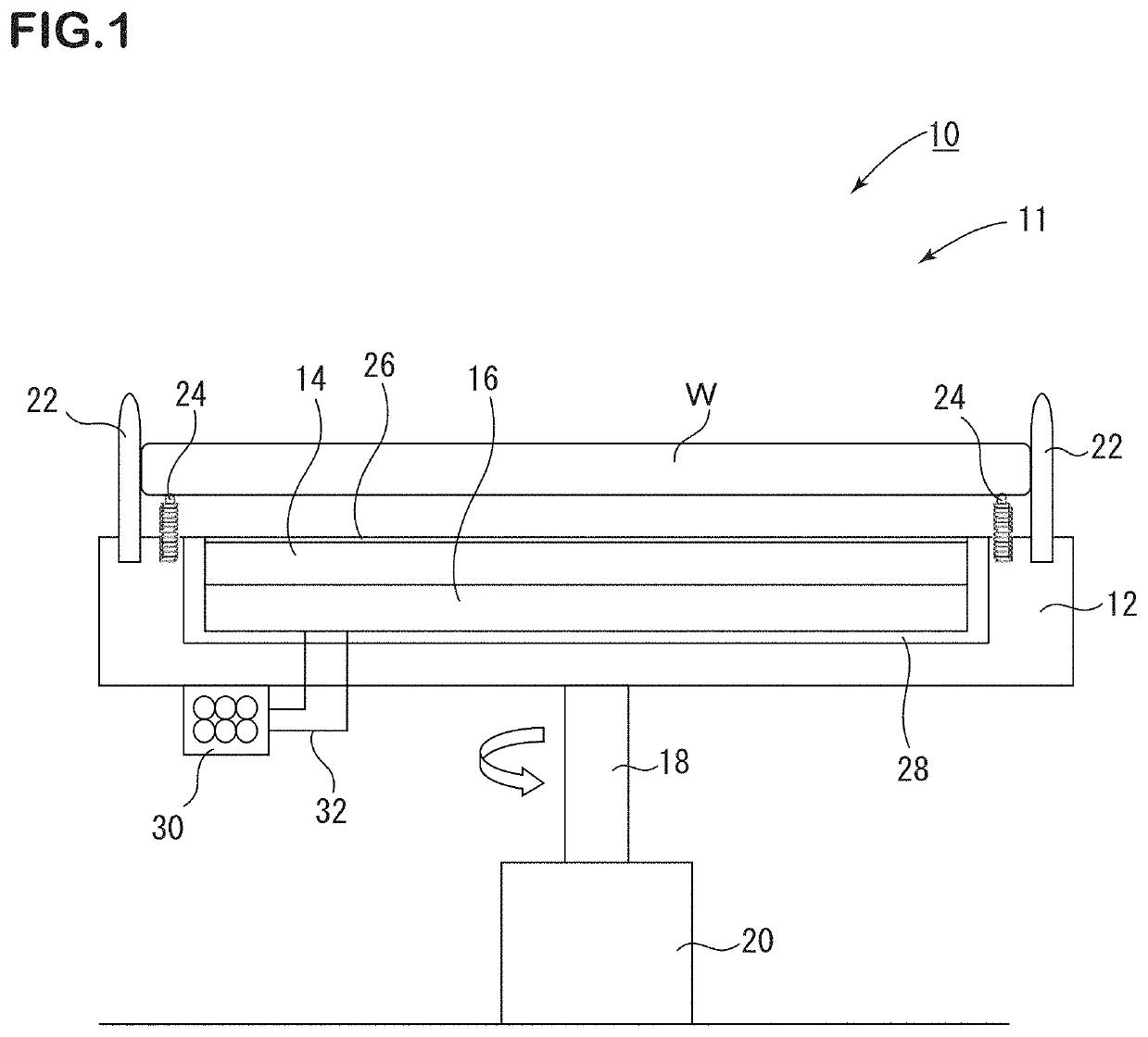
[0021]In FIG. 1, a wafer heating and holding mechanism for a rotary table according to the present invention is denoted by a reference symbol 10. The wafer heating and holding mechanism 10 for the rotary table is a wafer heating and holding mechanism for a rotary table of a wafer rotating and holding device 11, and comprises: a rotary shaft 18; a rotary table 12 placed on an end of the rotary shaft 18 and configured to hold a wafer W on an upper surface of the rotary table 12; a drive motor 20 configured to supply motive power to the rotary shaft 18; and heating means 14 provided above the rotary table 12 and below the wafer W without being in contact with ...


PUM

PropertyMeasurementUnit
temperatureaaaaaaaaaa
circumferenceaaaaaaaaaa
motive poweraaaaaaaaaa

Abstract

Provided are a wafer heating and holding mechanism for a rotary table, a wafer heating method for a rotary table, and a wafer rotating and holding device with which a wafer put on a rotary table can be heated while being rotated stably under a state in which an in-plane temperature distribution of the wafer is maintained. The wafer heating and holding mechanism for a rotary table of a wafer rotating and holding device comprises: a rotary shaft; a rotary table placed on an end of the rotary shaft and configured to hold a wafer on an upper surface of the rotary table; a drive motor configured to supply motive power to the rotary shaft; and a heater provided above the rotary table and below the wafer while avoiding contact with the wafer to heat the wafer.

Description

TECHNICAL FIELD[0001]The present invention relates to a wafer heating and holding mechanism and method for a rotary table of a wafer rotating and holding device, and to a wafer rotating and holding device.BACKGROUND ART[0002]Hitherto, in semiconductor manufacturing processes, there are an increasing number of steps (also called “spin processes”) in which various kinds of processing are performed while a semiconductor wafer made of, for example, silicon is rotated, such as spin etching, spin drying, and spin coating. As specific devices, there are known wafer rotating and holding devices such as a spin etching device, a spin drying device, and a spin coating device. Further, as examples of processing to be performed on a wafer surface in manufacturing processes for a device, there can be given, in addition to etching processing for removing a damaged layer after back-grinding, applying developer to the wafer, developing processing on the wafer, which has a surface that has circuit pa...

Claims


Application Information

Patent Timeline
Patent Type & Authority Patents(United States)
IPC IPC(8): H01L21/67H01L21/687H05B6/10G03F7/20H01L21/324H05B6/06H01L21/027H01L21/304
CPCH01L21/67109G03F7/70716H01L21/027H01L21/304H01L21/324H01L21/67103H01L21/68764H05B6/06H05B6/107
Inventor YOSHIDA, OSAMUTAMURA, MASAKINAGAI, HIDEAKI
Owner MIMASU SEMICON IND CO LTD
Why Eureka
Try Eureka