
Loudspeaker system, loudspeaker system component, and audio system

a loudspeaker and component technology, applied in the field of loudspeaker systems, can solve the problems of deteriorating acoustics, affecting the safety of passengers, and affecting so as to improve the sound quality, improve the safety of vehicles, and shorten the distance

Active Publication Date: 2021-08-10
PANASONIC INTELLECTUAL PROPERTY MANAGEMENT CO LTD
View PDF10 Cites 0 Cited by
  • Summary
  • Abstract
  • Description
  • Claims
  • Application Information

AI Technical Summary

Benefits of technology

This configuration enhances sound quality while ensuring safety by preventing the loudspeaker system from projecting into the cabin and maintaining structural integrity during external forces, thus improving both acoustic performance and safety.

Problems solved by technology

In this case, the body of the vehicle may generate unnecessary vibration, thereby deteriorating reproduced sound quality.
PTL (Patent Literature) 1 discloses a problem in which when a loudspeaker is directly embedded into an inner space of a vehicle door through an attachment hole in an inner wall panel in the vehicle door having a double wall structure, sound waves inside the inner space cause resonance phenomena, thereby deteriorating acoustics.
However, when a large-sized structure such as a loudspeaker enclosure is embedded in the internal space in the vehicle door, external force applied to the outer panel is transmitted to the inner panel via the structure in the internal space, so that the inner panel or another member is possibly deformed or broken to be in contact with passengers.

Method used


Image

  • Loudspeaker system, loudspeaker system component, and audio system
  • Loudspeaker system, loudspeaker system component, and audio system
  • Loudspeaker system, loudspeaker system component, and audio system

Examples


first exemplary embodiment

1. First Exemplary Embodiment

[0068]Hereinafter, a first exemplary embodiment will be described with reference to FIG. 1 to FIG. 17.

1-1. Schematic Configuration

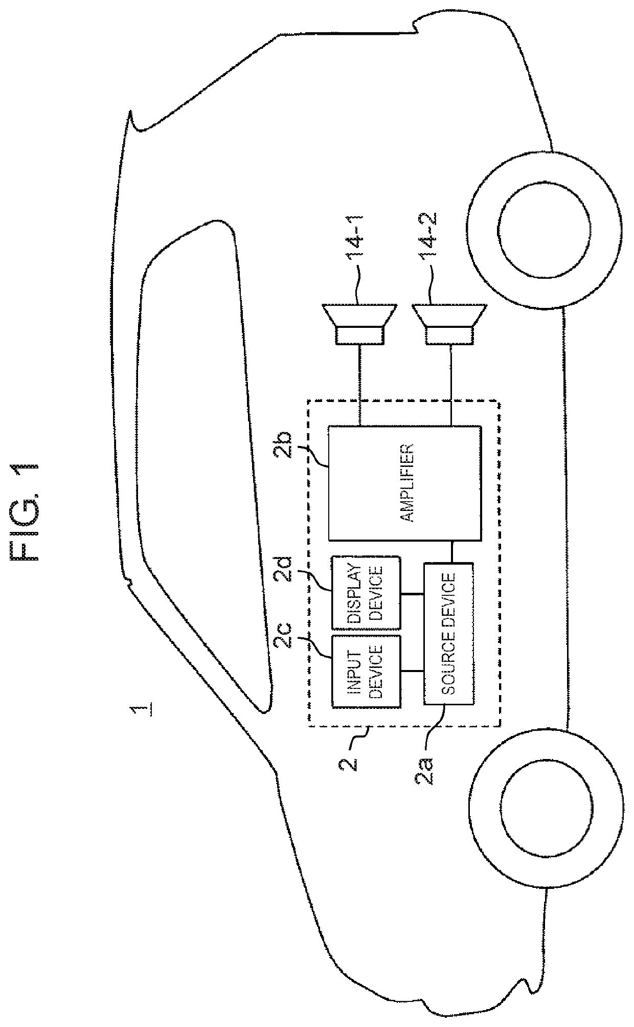
[0069]FIG. 1 is a block diagram illustrating a configuration of an automobile in which an audio system according to a first exemplary embodiment is mounted. In automobile 1 in FIG. 1, an audio system including audio signal processing device 2 and a plurality of loudspeaker drive units 14-1 and 14-2 that are connected to audio signal processing device 2 is mounted. Audio signal processing device 2 includes source device 2a, amplifier 2b, input device 2c, and display device 2d. Source device 2a includes a sound signal source such as a tuner of radio broadcasting and / or television broadcasting, a player such as a compact disk (CD), a digital video disk (DVD), and / or a Blu-ray disk (BD), and a portable media player. Source device 2a sends a sound signal obtained from the sound signal source to amplifier 2b. Source device 2a operat...

first example

1-3. First Example

[0091]Next, a loudspeaker system according to a first example of the first exemplary embodiment will be described with reference to FIG. 13 to FIG. 16B.

[0092]1-3-1. Configuration of First Example

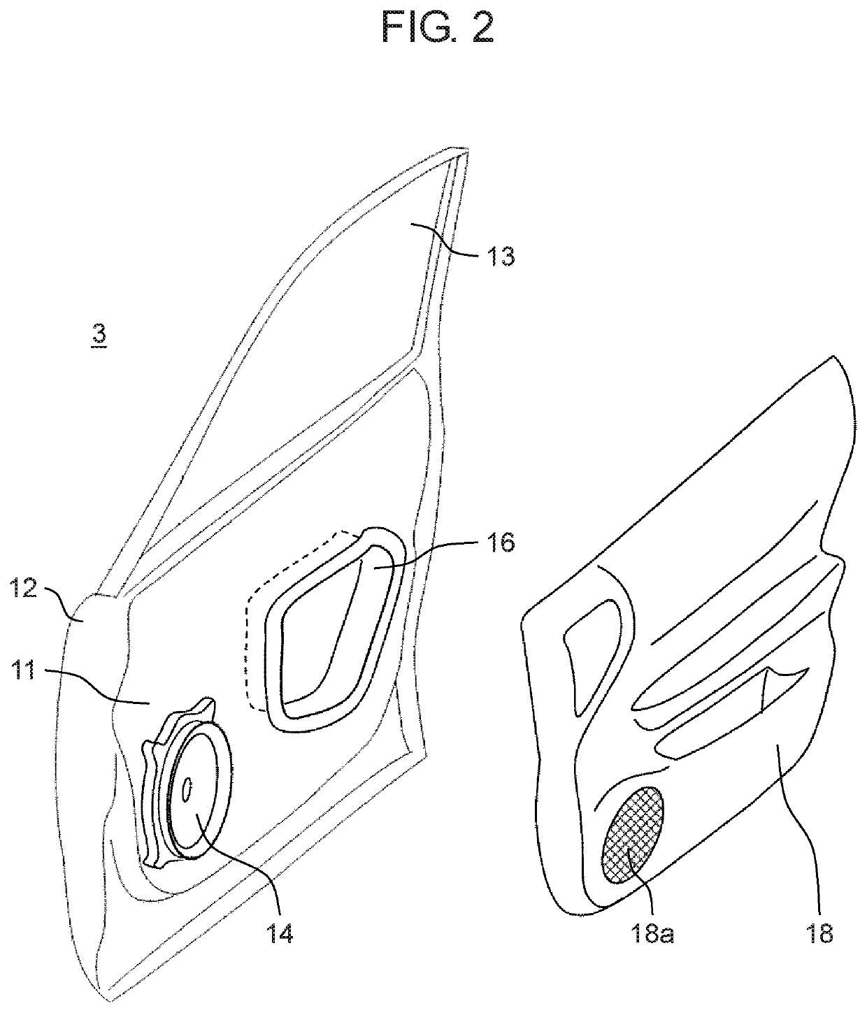
[0093]FIG. 13 is a sectional view illustrating a configuration of the loudspeaker system according to the first example of the first exemplary embodiment. The loudspeaker system in FIG. 13 is an example of the loudspeaker system in FIG. 4. As described with reference to FIG. 1 to FIG. 3, the loudspeaker system in FIG. 13 is disposed in door 3 tangent to the cabin space of automobile 1.

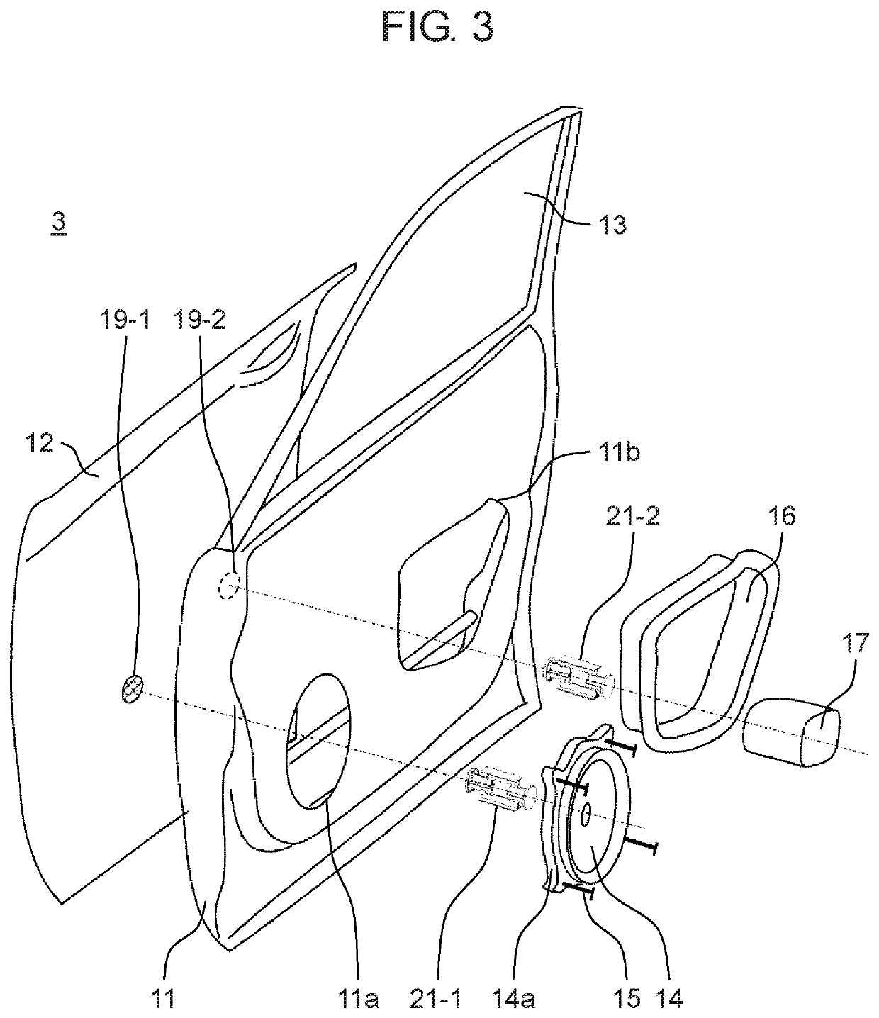
[0094]The loudspeaker system in FIG. 13 includes inner panel 11, outer panel 12, loudspeaker drive unit 14, fastening members 15, interior panel 18, loudspeaker grill 18a, flexible member 19, and coupling member 21. As described above, outer panel 12 is disposed to face the outside of automobile 1, and inner panel 11 is disposed inward from outer panel 12. Interior panel 18 is disposed to face...

second example

1-4. Second Example

[0109]Next, a loudspeaker system according to a second example of the first exemplary embodiment will be described with reference to FIG. 17.

[0110][1-4-1. Configuration of Second Example]

[0111]FIG. 17 is a sectional view illustrating a configuration of the loudspeaker system according to the second example of the first exemplary embodiment. The loudspeaker system in FIG. 17 is an example of the loudspeaker system in FIG. 5. As described with reference to FIG. 1 to FIG. 3, the loudspeaker system in FIG. 17 is disposed in door 3 tangent to the cabin space of automobile 1.

[0112]The loudspeaker system in FIG. 17 includes inner panel 11, outer panel 12, lid member 16, support member 17, interior panel 18, flexible member 19, and coupling member 21.

[0113]Lid member 16 is fixed to inner panel 11 at a position of the service hole (opening 11b in FIG. 3) of inner panel 11. Coupling member 21 is coupled to lid member 16 to be indirectly coupled to inner panel 11, thereby co...


PUM


Abstract

A loudspeaker system includes a housing including a first housing portion and a second housing portion that are plate-shaped and face each other, a loudspeaker drive unit fixed to the first housing portion, and a coupling member that is rigid and couples the first housing portion and the second housing portion to each other inside the housing. The coupling member includes a first end that is directly or indirectly coupled to the first housing portion and a second end that is directly or indirectly coupled to the second housing portion. When second force is applied to the coupling member, the second force being smaller than first force that irreversibly deforms or breaks a coupling portion between the coupling member and the first housing portion, the coupling member is irreversibly deformed or broken so as to shorten a distance between the first end and the second end of the coupling member.

Description

BACKGROUND1. Technical Field[0001]The present disclosure relates to a loudspeaker system including a loudspeaker drive unit and a housing. The present disclosure further relates to a loudspeaker system component for such a loudspeaker system, and relates to an audio system including at least one of such a loudspeaker system.2. Description of the Related Art[0002]An audio system mounted on a vehicle such as an automobile includes a loudspeaker drive unit embedded into a body of the vehicle in some cases. The loudspeaker drive unit is fixed to the body of the vehicle, and the body of the vehicle is used as a housing of the loudspeaker system. In this case, the body of the vehicle may generate unnecessary vibration, thereby deteriorating reproduced sound quality.[0003]PTL (Patent Literature) 1 discloses a problem in which when a loudspeaker is directly embedded into an inner space of a vehicle door through an attachment hole in an inner wall panel in the vehicle door having a double wa...

Claims


Application Information

Patent Timeline
Patent Type & Authority Patents(United States)
IPC IPC(8): H04R1/02B60R11/02H04R9/02B60R11/00
CPCH04R1/025B60R11/0217H04R1/023H04R9/025B60R2011/0021H04R2499/13B60R21/055B60J5/04H04R1/2888
Inventor FUJIMOTO, KEISUKESANO, KOJIMIYAMOTO, YASUNORIKOIDO, TEPPEI
Owner PANASONIC INTELLECTUAL PROPERTY MANAGEMENT CO LTD
Learn More