Method for measuring a behavior of a MEMS device

a technology of mems device and behavior, which is applied in the field of mems device behavior measurement, can solve the problems of gyroscope, major malfunction of mems device, and unreliable data, and achieve the effect of reducing the width of the air gap

Active Publication Date: 2021-10-05
TDK CORPARATION
View PDF56 Cites 0 Cited by
  • Summary
  • Abstract
  • Description
  • Claims
  • Application Information

AI Technical Summary

Benefits of technology

[0011]Accordingly, the method allows evaluating the accuracy of the data recorded by the inertial sensor when a vibration is applied to the MEMS device. Thus, the method may help to evaluate if an inertial sensor is able to provide reliable data even when a vibration is applied to the MEMS device. The method may also help to evaluate a performance of a damping of the MEMS device.
[0044]Further embodiments provide a method for measuring the behavior of an MEMS device comprising an inertial sensor, wherein the method comprises the step of applying a vibration to the inertial sensor and measuring the attenuation of the vibration using a laser Doppler vibrometer. The method using the laser Doppler vibrometer is more complicated and is less suitable for mass production than the method according to the first aspect. However, it may provide an improved accuracy. In a mass production of a multitude of MEMS devices, a measurement of the behavior using a laser Doppler vibrometer may be performed for a control sample comprising only a small number of MEMS devices.

Problems solved by technology

It is known that an inertial sensor, for example, a gyroscope, may provide unreliable data when a disturbance, e.g., vibration, is applied to the inertial sensor, in particular when the frequency of the disturbance is close to the resonance frequency of the inertial sensor.
Thus, sound sources or other external vibration sources may cause a major malfunction of the MEMS device which can be difficult to counter with digital filters or sensor fusion algorithms alone.

Method used


Image

  • Method for measuring a behavior of a MEMS device
  • Method for measuring a behavior of a MEMS device
  • Method for measuring a behavior of a MEMS device

Examples


Embodiment Construction

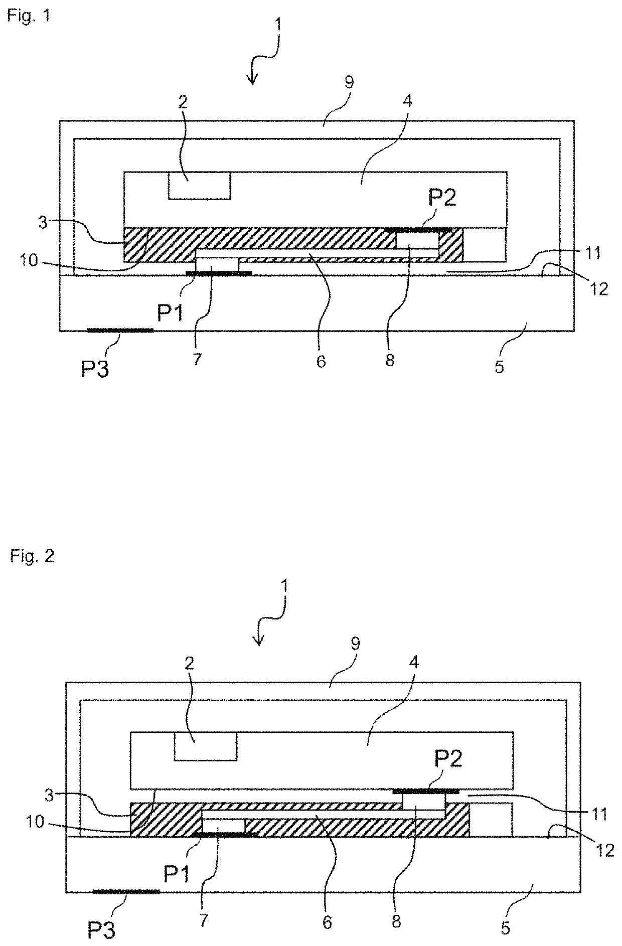
[0051]A method for measuring a behavior of a MEMS device 1 comprising an inertial sensor 2 is disclosed. The behavior may, in particular, be a mechanical attenuation behavior in response to a vibration applied to the MEMS device 1. Such a measurement is particularly relevant for a MEMS device 1 which comprises a damping structure 3 configured to attenuate a vibration of the inertial sensor 2. FIGS. 1 and 2 show such a MEMS device 1.

[0052]It is the purpose of the measurement to evaluate the performance of the MEMS device 1 when the MEMS device 1 is subjected to a mechanical disturbance, e.g., a vibration. The measurement is designed to determine if the inertial sensor 2 can provide reliable information even if a vibration is applied to the MEMS device 1. Moreover, the measurement is designed to determine an attenuation of a vibration of the MEMS device 1. For example, the measurement setup is designed to determine how long it takes, after the disappearance of a disturbance in form of...


PUM


Abstract

A method for measuring a behavior of a MEMS device is disclosed. In an embodiment a method includes mounting the MEMS device to a testing apparatus that comprises a vibration source, wherein the MEMS device comprises a 6-axis or 9-axis inertial sensor, applying a vibration to the MEMS device by the vibration source and simultaneously moving the testing apparatus according to a predefined movement pattern, reading output data provided by the inertial sensor and comparing the output data to the predefined movement pattern and / or reading output data provided by the inertial sensor and calculating a frequency response curve of the inertial sensor.

Description

[0001]This patent application is a national phase filing under section 371 of PCT / EP2018 / 068649, filed Jul. 10, 2018, which claims the priority of German patent application 102017115667.4, filed Jul. 12, 2017, each of which is incorporated herein by reference in its entirety.TECHNICAL FIELD[0002]The present invention relates to a method for measuring a behavior of a MEMS device comprising an inertial sensor. The behavior of the MEMS device that is measured by this method may be a mechanical attenuation behavior in response to a vibration being applied to the MEMS device.BACKGROUND[0003]It is known that an inertial sensor, for example, a gyroscope, may provide unreliable data when a disturbance, e.g., vibration, is applied to the inertial sensor, in particular when the frequency of the disturbance is close to the resonance frequency of the inertial sensor. Due to the ongoing trend for further miniaturization, in most MEMS devices there is almost no space for damping material or struc...

Claims


Application Information

Patent Timeline
Patent Type & Authority Patents(United States)
IPC IPC(8): G01C19/5712G01C19/5719B81B7/02G01P15/08G01P15/18
CPCG01C19/5719B81B7/02G01C19/5712G01P15/0802G01P15/18B81B2201/0235B81B2201/0242B81C99/0045B81C99/00G01C19/56G01P21/00
Inventor BARBUL, ANDREASPAHL, WOLFGANG
Owner TDK CORPARATION
Why Eureka
Try Eureka