Composite piston machine combining rotary oscillating and pendular movements

a piston machine and piston technology, applied in the field of piston machines, can solve the problems of low performance that cannot be overcome, and achieve the effect of increasing volumetric performance and maximum pressur

Active Publication Date: 2021-10-12
MOJICO HECTOR JOSE
View PDF3 Cites 0 Cited by
  • Summary
  • Abstract
  • Description
  • Claims
  • Application Information

AI Technical Summary

Benefits of technology

[0005]The main object of this invention is to obtain a machine with a high volumetric performance for high pressure, with a simple mechanism of high mechanical performance that minimizes the incorporation of lubricant into the circulating fluid.
[0008]The high mechanical performance of this machine is due to the fact that the few moving parts perform combined movements of low friction and easy lubrication, obtaining sealing surfaces between them and with the fixed parts, of great tightness. The possibility of balancing the machine is favored because the sets of moving parts are arranged at 180° to each other, in their respective working chambers. This allows that even at high revs, vibrations are minimal. The effective work that is achieved in each cycle and the large number of these (R.P.M.), makes it possible to manufacture machines of reduced dimensions in relation with its power and therefore lower manufacturing costs.
[0010]d) In each working chamber, one or more rotors, each linked to a shaft, rotate 180° out of phase with each other, both concentric to the first cylindrical sector and at a minimum distance from it, forming closing surfaces that separate the chambers in inlet chambers and outlet chambers of variable volume.e) The rotors have radially carved piston guides through which the composite pistons, made up of piston bodies and piston heads, move oscillating at each turn, forming two moving assemblies of combined movement both oscillatory and swinging, which makes it possible for the piston head to adapt to the curvature of the second cylindrical sector, forming a closing surface that limits the variable volume chambers.f) The lids (b) and the separator (c) have carved cavities for bearings and also skid guides, where the skids move, which guide the oscillatory movement of the composite pistons, limiting the action of centrifugal force and maintaining the minimum distance between the inner cavity's surface and the piston heads.g) On both sides of the first cylindrical sector's surface, on the wall of the main body, the inlet and outlet ports for the propellant or propelled gases or liquids are located.h) In each cycle of the rotary displacement, each composite piston produces chambers of variable volume, increasing the inlet chamber, and decreasing the outlet chamber and, when passing through the inlet and outlet ports, obstructs the outlet and inlet of driven or impeller gases or liquids.
[0011]The most relevant feature of this machine is the mechanical performance that is achieved with minimal friction and the sealing that the inner surfaces of the main body achieve with the rotors and with the composite pistons, which allows to increase the volumetric performance and maximum pressures.

Problems solved by technology

Despite this, they have not been able to overcome the problems of low performance, due to friction losses and manufacturing costs caused by the large number of moving parts and in general the complexity of their manufacture.

Method used


Image

  • Composite piston machine combining rotary oscillating and pendular movements
  • Composite piston machine combining rotary oscillating and pendular movements
  • Composite piston machine combining rotary oscillating and pendular movements

Examples


Embodiment Construction

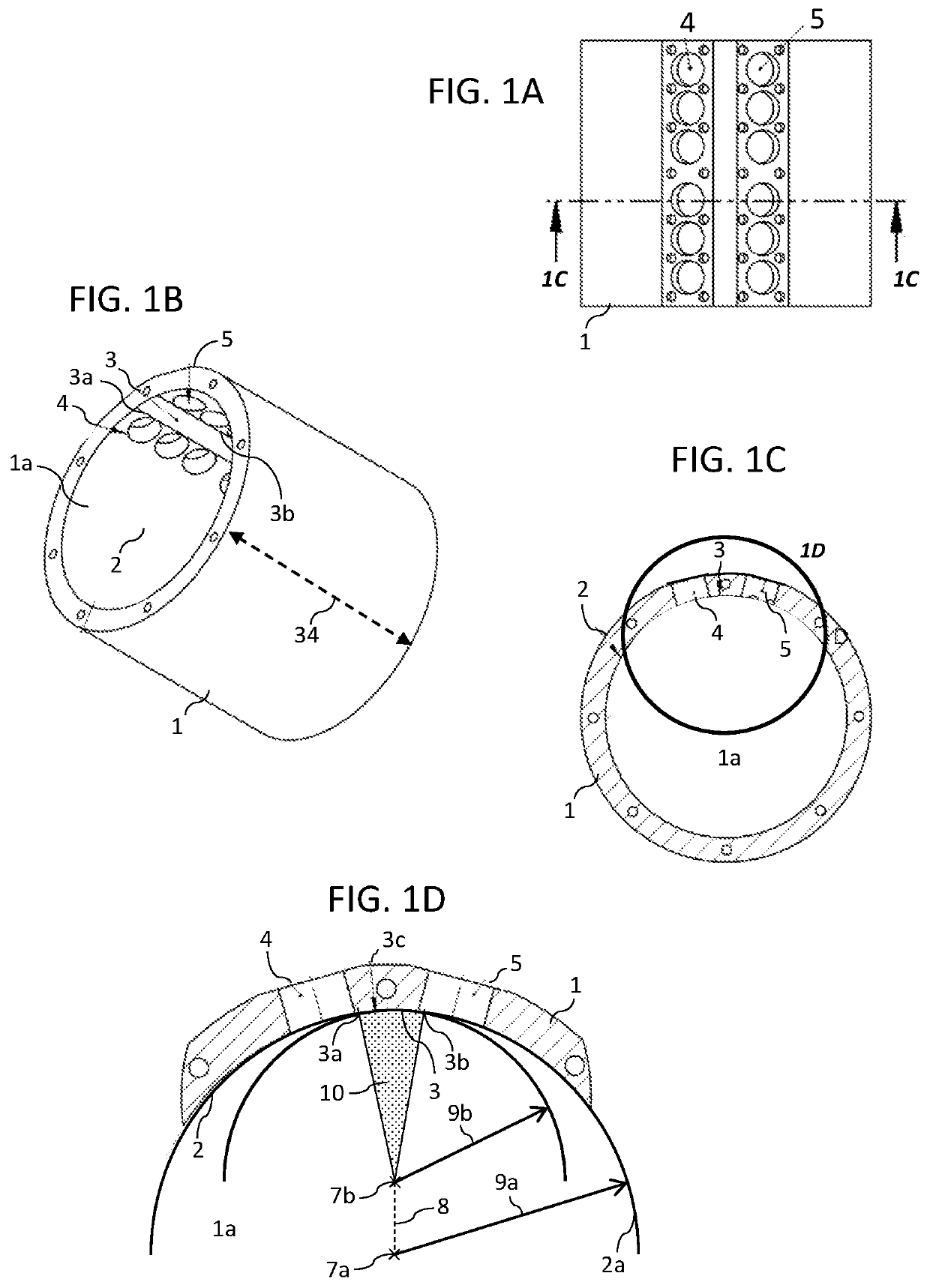
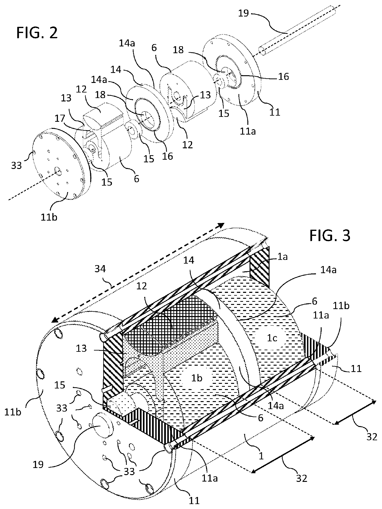
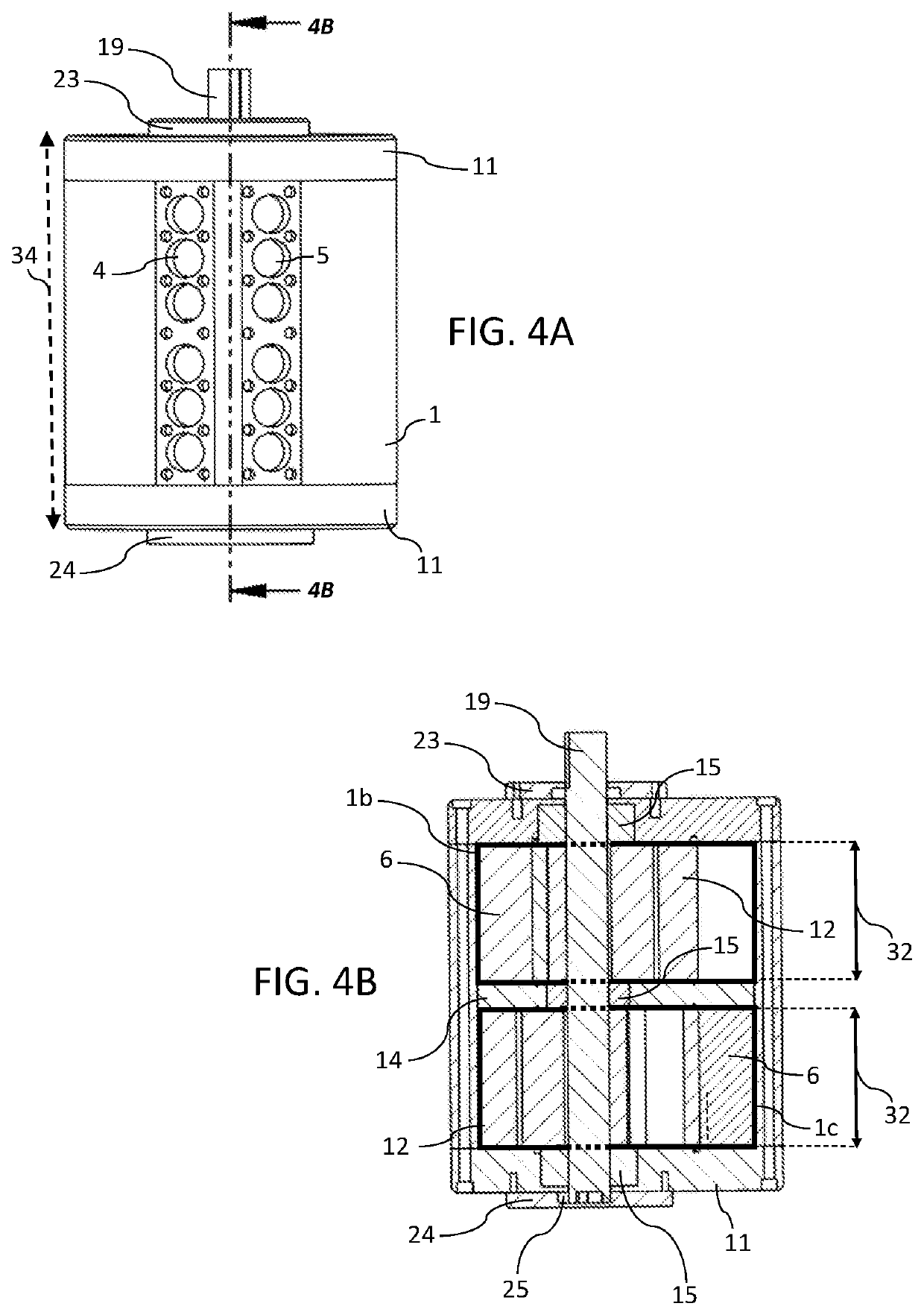
[0042]Disclosed is a composite piston machine that combines three different kinds of movements for an improved performance: rotary, oscillating and pendular. To achieve this, the machine includes a main body having inlet and outlet ports that allow the passage of gasses and / or liquids into and out from a generally cylindrical inner cavity carved inside this main body. This inner cavity is formed by two cylindrical sectors of different center points and radiuses. The first cylindrical sector, which encompasses the shortest area between the inlet and the outlet ports, is eccentric with respect to the main body while the second cylindrical sector, which encompasses the rest of the inner cavity, is centered on it. The machine also includes two lids and a separator that divides the main body into two compartments, obtaining working chambers of equal volume. Each working chamber has inside of it a moving assembly including a rotor, and a composite piston formed by a piston head and a pist...


PUM


Abstract

A composite piston machine has two moving assemblies of a rotor and a composite piston placed 180° out of phase with each other and linked to a shaft eccentrically placed inside the inner cavity of a main body that has ports for the inlet and outlet of fluids from it. This inner cavity is covered by two lids and divided in two working chambers by a separator. The composite pistons move following the rotation of the rotors while oscillating with respect of them and following the path of skid guides carved in separator and lids, dividing each working chamber in inlet and outlet chambers of variable volume, and intermittently obstructing the inlet and outlet of fluids from the inner cavity through the ports. The machine is designed for compressing gases or pumping liquids and can also operate as an engine driven by compressed gases or with pressurized liquids.

Description

CROSS REFERENCE TO RELATED APPLICATIONS[0001]This patent application claims foreign priority under the Paris Convention of the Argentinian Patent Application No. 20190103633, filed on Dec. 12, 2019 the contents of which are incorporated by reference herein.TECHNICAL FIELD[0002]The present invention relates in general to a piston machine, and, more specifically, to a composite piston machine with combined movements: rotary, oscillating and pendular, which can be designed and used as a pneumatic or hydraulic motor, compressor, hydraulic pump, vacuum pump or similar.BACKGROUND OF THE INVENTION[0003]In general, and as is known, alternative machines are the most developed and useful in the realization of motors and compressors. Despite this, they have not been able to overcome the problems of low performance, due to friction losses and manufacturing costs caused by the large number of moving parts and in general the complexity of their manufacture.[0004]Among other machines that have had...

Claims


Application Information

Patent Timeline
Patent Type & Authority Patents(United States)
IPC IPC(8): F01C11/00F01C21/08
CPCF01C11/002F01C21/08F01C21/0809F01C21/106F04C2/3442F04C11/001
Inventor MOJICO, HÉCTOR JOSÉ
Owner MOJICO HECTOR JOSE
Why Eureka
Try Eureka