Solid electrolytic capacitor

a solid electrolytic capacitor and capacitor technology, applied in the manufacture of electrolytic capacitors, capacitor dielectric layers, electrolytic capacitors, etc., can solve the problems of affecting reliability and the disadvantage of the device as a whole, and achieve the effects of high reliability, reduced or prevented thermal stress, and increased volume occupied by capacitor elements

Active Publication Date: 2021-11-09
MURATA MFG CO LTD
View PDF32 Cites 3 Cited by
  • Summary
  • Abstract
  • Description
  • Claims
  • Application Information

AI Technical Summary

Benefits of technology

[0007]The present invention is made to solve the above problem, and aims to provide a highly reliable solid electrolytic capacitor in which cracking to a resin molded body from stress caused by thermal stress can be reduced or prevented while the volume occupied by the capacitor elements is increased.
[0009]The present invention provides a highly reliable solid electrolytic capacitor in which cracking to a resin molded body from stress caused by thermal stress can be reduced or prevented while the volume occupied by the capacitor elements is increased.

Problems solved by technology

Yet, when the lead frame that does not contribute to capacitor characteristics is provided in the sealing resin, it is disadvantageous in terms of volume capacity density of the device as a whole.
When the area occupied by capacitor elements in such a structure is maximized, cracking may occur due to strain caused by the difference in linear expansion coefficient between the capacitor elements and the exterior resin, adversely affecting the reliability.

Method used


Image

  • Solid electrolytic capacitor
  • Solid electrolytic capacitor
  • Solid electrolytic capacitor

Examples


Embodiment Construction

[0029]The solid electrolytic capacitor of the present invention is described below.

[0030]The present invention is not limited to the following preferred embodiments, and may be suitably modified without departing from the gist of the present invention. Combinations of two or more preferred features described in the following preferred features are also within the scope of the present invention.

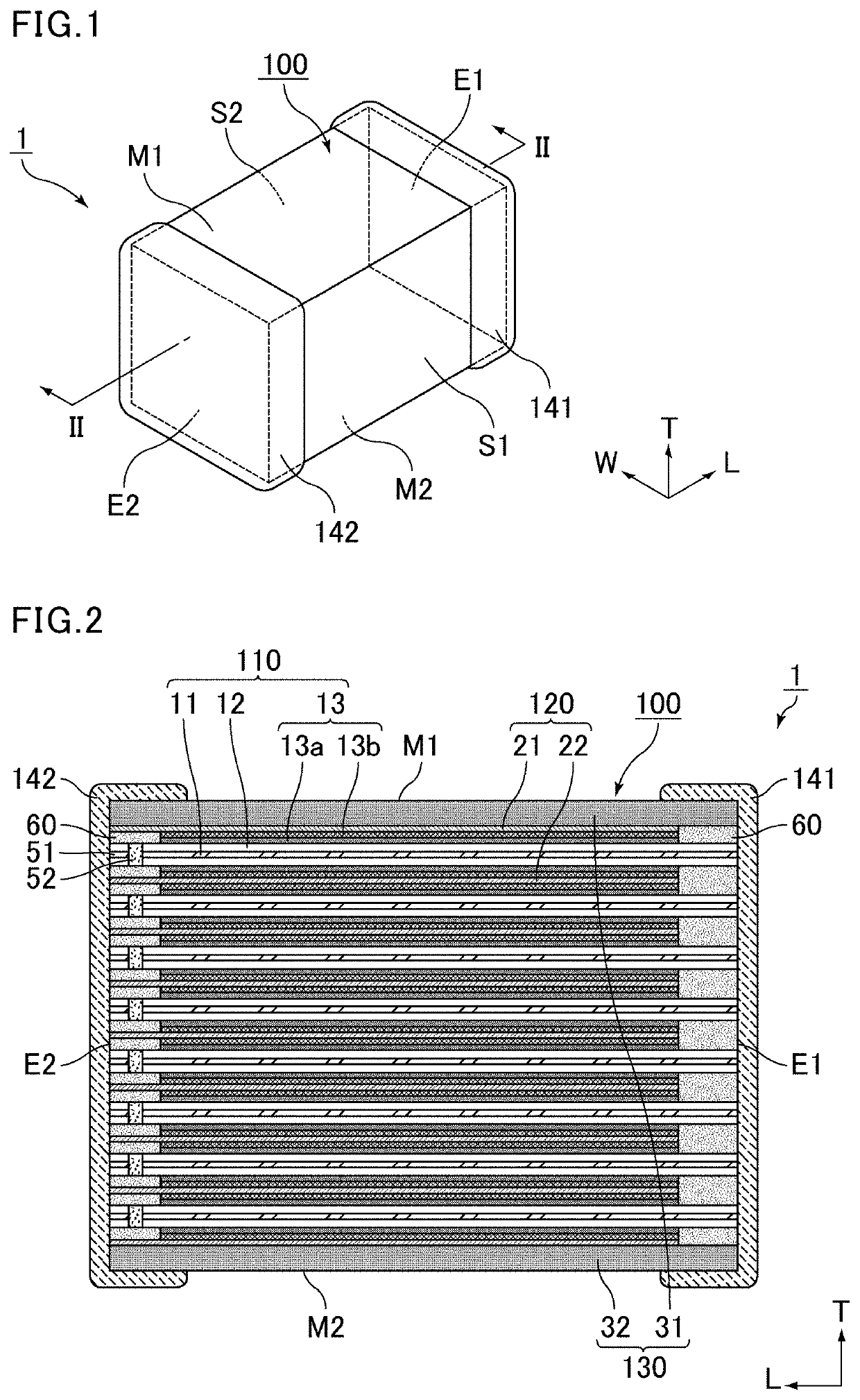
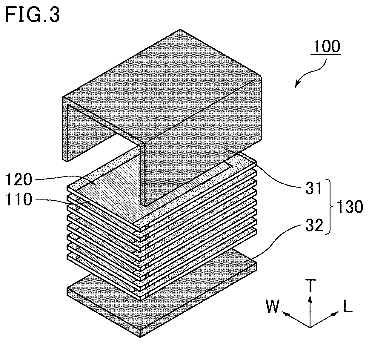
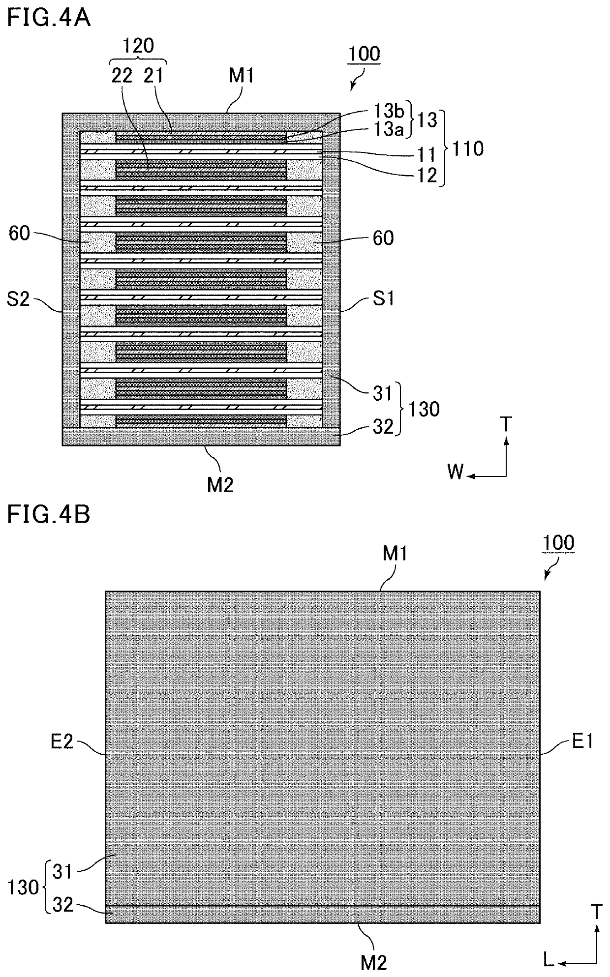
[0031]In the solid electrolytic capacitor of the present invention, a sealing body includes a first resin molded body that encloses capacitor elements and cathode lead-out layers from a first main surface side of a capacitor element laminate so as to define at least the first main surface of the capacitor element laminate, and a second resin molded body that encloses the capacitor elements and the cathode lead-out layers from a second main surface side of the capacitor element laminate so as to define at least the second main surface of the capacitor element laminate. The first resin molded bo...


PUM

PropertyMeasurementUnit
thicknessaaaaaaaaaa
thicknessaaaaaaaaaa
thicknessaaaaaaaaaa

Abstract

A solid electrolytic capacitor that includes a capacitor element laminate, a first external electrode, and a second external electrode. The capacitor element laminate includes capacitor elements, cathode lead-out layers, and a sealing body. At least one of the capacitor elements includes an anode foil, dielectric layers, and cathode layers. The first external electrode is connected to the anode foil exposed at the first end surface of the capacitor element laminate. The second external electrode is connected to the cathode lead-out layers exposed at the second end surface of the capacitor element laminate. The sealing body includes a first resin molded body and a second resin molded body. The first resin molded body and the second resin molded body are made of the same insulating material.

Description

CROSS REFERENCE TO RELATED APPLICATIONS[0001]The present application claims priority to Japanese Patent Application No. 2019-054615, filed Mar. 22, 2019, the entire content of which is incorporated herein by reference.FIELD OF THE INVENTION[0002]The present invention relates to a solid electrolytic capacitor.BACKGROUND OF THE INVENTION[0003]Patent Literature 1 (JP 2007-180160 A) discloses a method of producing a capacitor chip (multilayer solid electrolytic capacitor) by enclosing a capacitor element laminate in resin. Patent Literature 1 aims to provide a technique that increases the range of the total allowable thickness of laminated capacitor elements to increase the capacitance, without causing poor appearance in the multilayer solid electrolytic capacitor.[0004]Patent Literature 2 (WO 2018 / 074408) discloses a solid electrolytic capacitor including a laminate of multiple units each including a valve-action metal substrate having a porous layer on a surface, a dielectric layer on...

Claims


Application Information

Patent Timeline
Patent Type & Authority Patents(United States)
IPC IPC(8): H01G9/10H01G9/15H01G9/00H01G9/07H01G9/055
CPCH01G9/15H01G9/0036H01G9/055H01G9/07H01G9/10H01G9/08H01G9/012H01G9/26H01G9/008
Inventor FURUKAWA, TAKESHISHIRAKAWA, SACHIKO
Owner MURATA MFG CO LTD
Why Eureka
Try Eureka