Electrical distribution system for personal water craft

a technology for electric distribution systems and personal watercraft, which is applied in the direction of vessel auxillary drives, three-or-more-wire dc circuits, canoes/kayaks, etc., can solve the problems of unsatisfactory electrical charge loss, boat cramping, and wires running through the area intended for the operator and/or cargo, so as to facilitate synchronization and minimize parasitic loss of electrical charge

Active Publication Date: 2021-11-23
SOUTHERN AUDIO SERVICES
View PDF1 Cites 0 Cited by
  • Summary
  • Abstract
  • Description
  • Claims
  • Application Information

AI Technical Summary

Benefits of technology

[0008]It is still another object of the invention to provide an electrical distribution system that is easy to install.
[0009]It is yet another object of the invention to provide an electrical distribution system that can be installed without compromising the integrity of a vessel with respect to water-tightness.
[0011]It is yet another object of the invention to provide an electronic distribution system that can easily synchronize with remote electronics for remote control of the system via the remote electronic device.
[0012]It is still another object of the invention to minimize parasitic loss of electrical charge when the electronic distribution system is not in use.
[0014]An electrical distribution system is disclosed. The primary components include a digital switching device, a series of power lines and either a control panel, at least one remote control device or both a control panel and one or more remote control devices. The digital switching device is preferably a bank of solid state relay switches controlled by a microcontroller or MCU. The control panel is also provided with an MCU. The MCU on the control panel communicates with the MCU in the digital switching device. This allows the signals from the control panel to be carried on a single communication cable to the digital switching device. That means there need only be one wire connecting the control panel to the digital switching device, significantly reducing the footprint of the control panel compared to prior art control panels. When a radio frequency (RF) receiver is provided, the electrical distribution system may receive signals from a remote control. Those signals will be transmitted to the MCU in the digital switching device, allowing the remote to control the relay bank in the same manner as the control panel. The remote control may be utilized in addition to or in lieu of the control panel. By utilizing Bluetooth or other similar protocols, the RF receiver may synchronize with third party electronic devices such as smart phones to allow the control signals to be sent from the third party electronic device to the RF receiver, which will then transmit them to the MCU in the digital switching device. Power lines run from the digital switching device to the various locations where power is desired. Quick connections between the power lines and the digital switching device make installation of the power lines easy to accomplish. An outlet configured to form a water tight seal with the hull exterior is also disclosed.

Problems solved by technology

That advantage becomes a disadvantage if the user desires to provide any electrically powered additions to the water craft.
If the operator wishes to carry food and drink, fishing and / or photographic equipment, or camping and other gear, the boats can become decidedly cramped.
Having wires running through the areas of the vessel intended for the operator and / or cargo is not desirable.
Batteries are heavy.
Accordingly, additional batteries are often not something that can be carried easily.
Likewise, a generator or recharging device will seldom be available.
Solar recharging devices are possible, but solar charging is slow.

Method used


Image

  • Electrical distribution system for personal water craft
  • Electrical distribution system for personal water craft
  • Electrical distribution system for personal water craft

Examples


Embodiment Construction

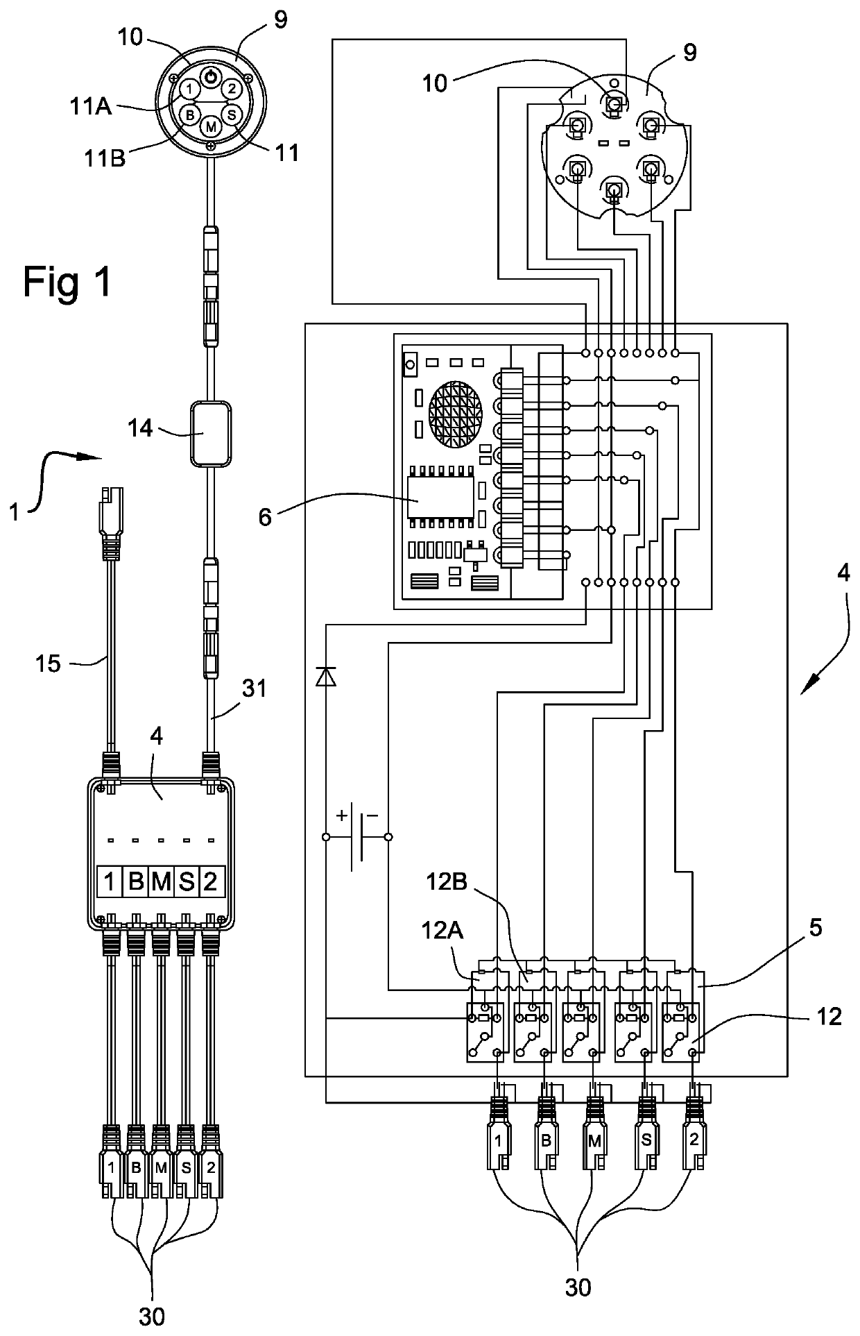
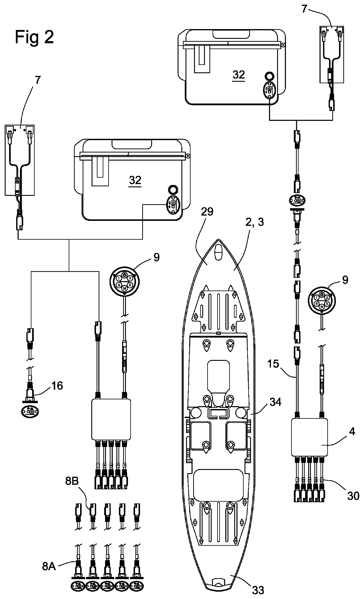
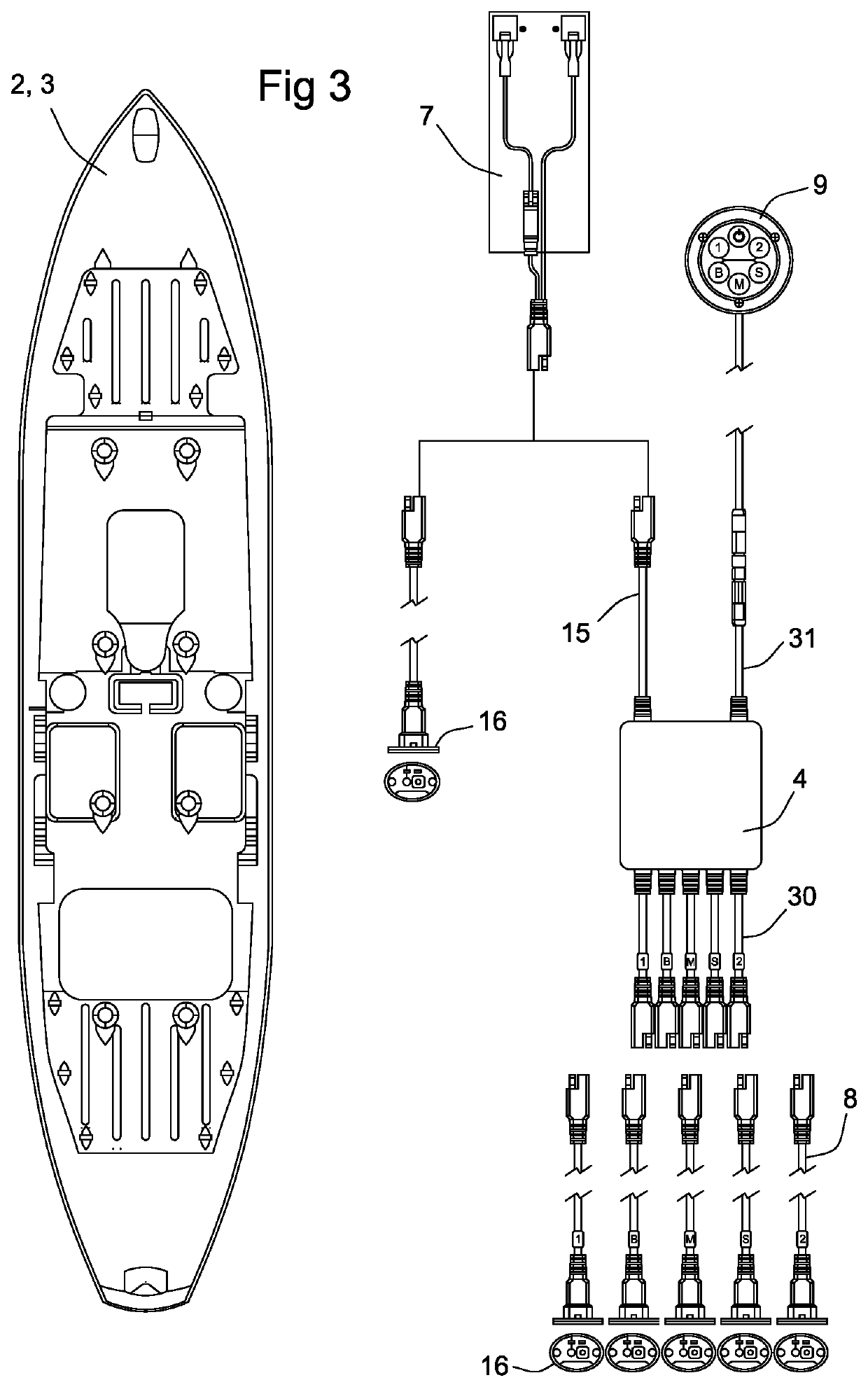
[0036]The invention comprises an electrical distribution system 1 designed particularly for kayaks 2 and other personal water craft 3. System 1 includes a digital switching device 4. Digital switching device 4 is preferably a solid state relay switch bank 5 with a microcontroller unit (MCU) 6. An MCU is essentially a mini-processor contained on a single chip. In the preferred embodiment it is configured to transfer 12 volt power from a battery 7 to a plurality of power lines 8. In the preferred embodiment there are five power lines 8, though greater or fewer could be provided as desired. A control panel 9 is also provided. Control panel 9 is electrically connected to relay switch bank 5. Control panel 9 is provided with a master power switch 10, which when deactivated powers off the entire system 1. Control panel 9 is provided with a separate switch 11 for each relay 12 within bank 5. Moving the first switch 11A to its on position activates the first relay 12A which energizes the fi...


PUM


Abstract

An electrical distribution system for personal water craft. The primary components include a digital switching device; a series of power lines; and one or more remote controls, a control panel, or both. The digital switching device is preferably a bank of solid state relay switches controlled by an MCU. The control panel also has an MCU. The control panel MCU communicates with the digital switching device MCU. This allows signals from the control panel to travel on a single communication cable to the digital switching device, significantly reducing the control panel footprint compared to prior art control panels. When a radio frequency (RF) receiver is provided, the electrical distribution system may receive signals from a remote control. The remote control may be utilized in addition to or in lieu of the control panel. Power lines run from the digital switching device to wherever power is desired in the vessel.

Description

PRIORITY CLAIM[0001]This application claims benefit of pending U.S. patent application Ser. No. 15 / 886,792, filed Feb. 1, 2018, which in turn claimed benefit to provisional U.S. Patent Application Ser. No. 62 / 453,236, filed Feb. 1, 2017, both of which are hereby incorporated by reference in their entirety.BACKGROUND OF THE INVENTIONField of the Invention[0002]The invention relates to electrical control and distribution systems in general and to electrical control and distribution systems in small personal water craft, in particular.Prior Art[0003]Small, personal water craft, such as kayaks are quite popular. They allow boaters the opportunity to reach shallow waters, difficult to access with larger craft. One of the features of the kayak that allows them to reach otherwise inaccessible waters is their small size and slight draft. That advantage becomes a disadvantage if the user desires to provide any electrically powered additions to the water craft. Space is at a premium in most k...

Claims


Application Information

Patent Timeline
Patent Type & Authority Patents(United States)
IPC IPC(8): B63B34/20B63J99/00B63J3/04B63B79/00B63J3/00B63B34/26
CPCB63B34/20B63J3/04B63J99/00B63B34/26B63B79/00B63J2003/002B63J2003/043B63B32/10H02J1/08H02J13/00026H02J13/00036H02J2310/42
Inventor JORDAN, JEFF BJORDAN, JON C
Owner SOUTHERN AUDIO SERVICES
Why Eureka
Try Eureka