
Brush assembly

a brush and lightning protection technology, applied in the direction of wind energy generation, motors, rotary current collectors, etc., can solve the problems of inconvenient assembly, inability to incorporate conventional brushes, and generator design subject to additional constraints

Active Publication Date: 2021-11-30
SIEMENS GAMESA RENEWABLE ENERGY AS
View PDF25 Cites 0 Cited by
  • Summary
  • Abstract
  • Description
  • Claims
  • Application Information

AI Technical Summary

Benefits of technology

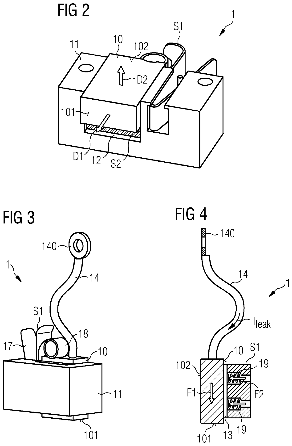
[0009]In a conventional brush assembly, the electric current is transferred to the brush by means of a brush cable that terminates in the body of the brush, and the current is then transferred between the first and second structures through a single brush face. In the inventive brush assembly, electric current is transferred to the brush through the second exposed brush face. An advantage of the inventive brush assembly is therefore a significantly lower impedance compared to a conventional brush assembly. The significantly lower impedance advantageously reduces the voltage drop at the interface between the first and second structures. Instead of channeling the electric current to a brush cable for transfer to the brush, it can pass directly through the brush body from one structure to the other, entering and exiting the brush through an exposed brush face.
[0010]Since the design of the inventive brush assembly remains similar to the design of conventional brush assemblies—with regard to the holder and the first displacement means—the cost of manufacturing the inventive brush assembly is essentially the same. However, because the inventive brush assembly is considerably more effective in safely transferring high transient currents, it is possible to use a reduced number of these brush assemblies in a large electrical machine, thereby reducing the costs of manufacture and also reducing the costs associated with regular maintenance procedures.
[0011]According to embodiments of the invention, the lightning protection circuit of a wind turbine comprises a first current path arrangement realized to provide a path for lightning current through the rotatory part of a wind turbine towards an interface to the stationary part of the wind turbine; a second current path arrangement realized to provide a path for lightning current through the stationary part of the wind turbine to ground; and an embodiment of the inventive brush assembly for electrically connecting the first current path arrangement to the second current path arrangement. The inventive brush assembly ensures that any lightning current sees only a low impedance at the interface between the rotatory part and the stationary part, and can be safely and reliably transported across this interface.
[0019]As indicated above, the exposed first brush face will be subject to wear, because it is continually pressed against the surface of the sliding structure. This means that the gradually diminishing remainder of the brush is moved slowly but steadily in the direction of the sliding structure. It is important not to obstruct this movement. Therefore, in a further exemplary embodiment of the invention, the second displacement means comprises a low-friction or frictionless contact to the brush. For example, if the second displacement means comprises a plate to press against the brush, this plate can be given a low-friction surface so that the brush can freely slide over the plate in the direction of the sliding structure. Similarly, a point contact or line contact between a rolling element and the brush will be inherently low-friction.
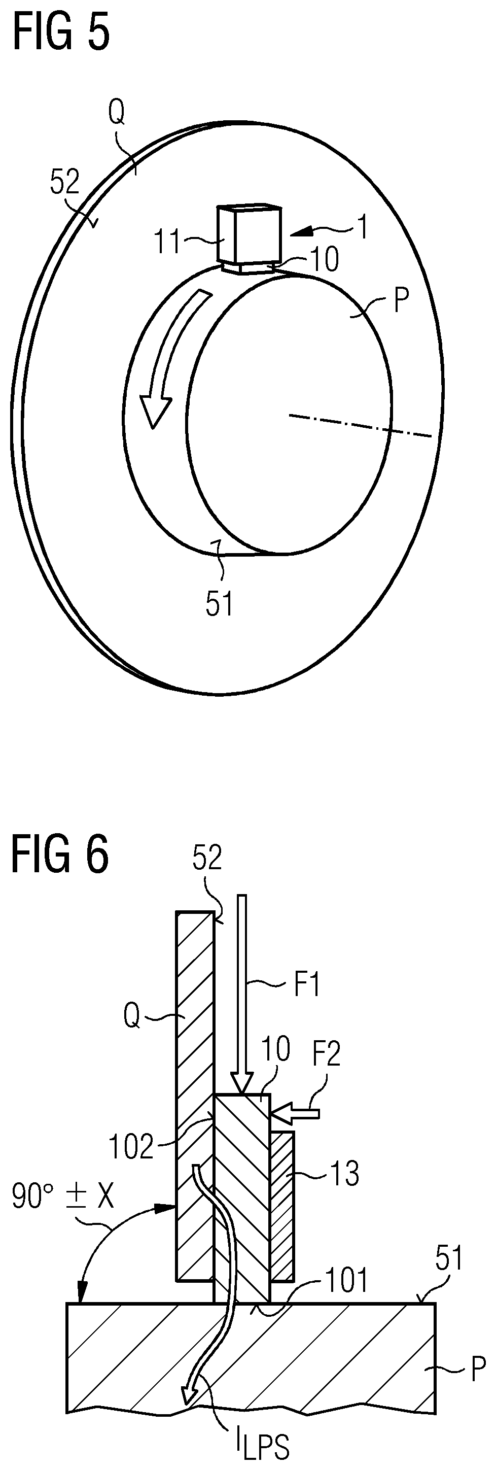
[0021]In an exemplary embodiment of the invention, the wind turbine comprises a lightning protection circuit in which the brush assembly is mounted at an interface between the generator rotor and a stationary part, for example a stationary generator housing, a rotor brake plate, a canopy or nacelle, etc. In a direct-drive wind turbine, for example, a brush assembly can be mounted at an interface between the outer rotor and a front plate of the stator. These parts can be made of steel and can therefore be inherently conductive, so that transfer of high lightning currents across this interface can be done safely and reliably.

Problems solved by technology

However, as generator designs become more compact, it is becoming increasingly difficult to incorporate the conventional brushes in the LPS in such a way that the brush assemblies can also be accessed for regular maintenance, since the carbon / graphite brushes wear down over time and need to be exchanged at regular intervals.
The need to include the plurality of brushes means that the generator design is subject to additional constraints, and this can require undesirable compromises to be made.
As indicated above, the exposed first brush face will be subject to wear, because it is continually pressed against the surface of the sliding structure.

Method used


Image

  • Brush assembly
  • Brush assembly
  • Brush assembly

Examples


Embodiment Construction

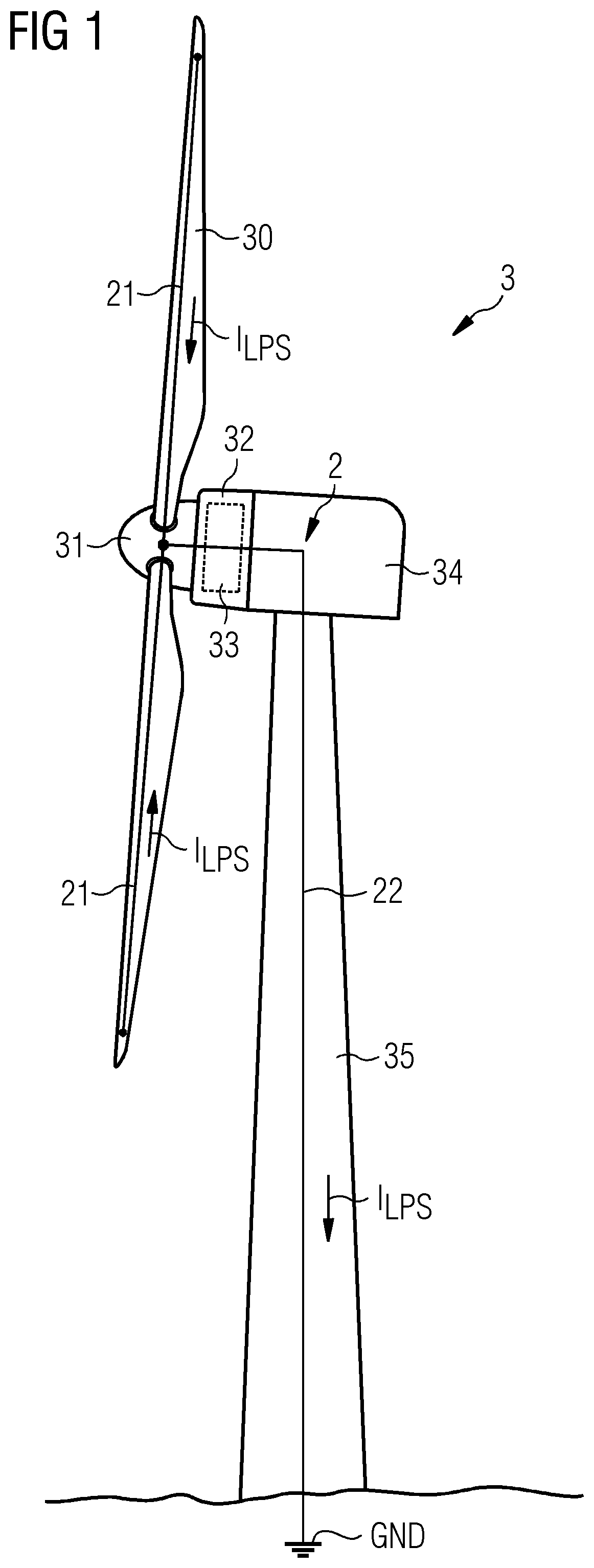
[0035]FIG. 1 is a simplified diagram of a direct-drive wind turbine 3 and its LPS 2. The aerodynamic rotor of the wind turbine comprises the rotor blades 30 mounted to the hub 31. The outer rotor 32 of the generator can be enclosed in a housing that rotates as one with the outer rotor 32. The diagram also shows a stationary canopy 34 or nacelle 34. The stator 33 of the generator is mounted in some way to a bedframe or fixed support, and connected to the rotor 32 by means of a bearing arrangement. The stationary part of the wind turbine 3 is mounted by means of a yaw interface at the top of a tower 35.

[0036]To safely conduct lightning current to ground, each rotor blade 30 is equipped with a number of receptors connected to a down conductor of a current path arrangement 21. A rotor blade down conductor is arranged in the interior of the blade 30. All down conductors of this current path arrangement 21 can convene in the hub 31, and the lightning current ILPS is transferred by an embo...


PUM


Abstract

Provided is a brush assembly for transferring lightning current between a first structure and a second structure, which brush assembly includes a holder realized for mounting to one of the two structures; a recess formed in the holder, which recess is shaped to accommodate a brush and to expose a first brush face; and a first displacement means arranged to move the first exposed brush face against a surface of the first structure; and wherein the recess is shaped to also expose a second brush face, and the brush assembly further includes a second displacement means arranged to move the second exposed brush face against a surface of the second structure. Further provided is a lightning protection circuit of a wind turbine; and a wind turbine.

Description

CROSS-REFERENCE TO RELATED APPLICATIONS[0001]This application claims priority to EP Application No. 182107840.9, having a filing date of Dec. 6, 2019, the entire contents of which are hereby incorporated by reference.FIELD OF TECHNOLOGY[0002]The following relates to a brush assembly, a lightning protection circuit, and a wind turbine.BACKGROUND[0003]Because of its height and generally exposed location, a wind turbine may receive frequent lightning strikes and must be equipped with a reliable lightning protection system (LPS) to prevent damage to its rotor blades, its electrical components, and its structural components. A wind turbine rotor blade is normally provided with one or more receptors on its outer surface that act to attract a lightning strike. Each receptor is connected to a download cable or “down conductor” extending through the blade interior. A down conductor usually extends from near the thin blade tip (at the outermost end of the blade) to the circular root (at the i...

Claims


Application Information

Patent Timeline
Patent Type & Authority Patents(United States)
IPC IPC(8): F03D80/30H01R39/38H01R39/40H01R39/26
CPCF03D80/30H01R39/381H01R39/40H01R39/26H01R39/38H01R39/383H01R39/64H02G13/40Y02E10/72
Inventor MICHAELSEN, CLAUSOLSEN, KAJ
Owner SIEMENS GAMESA RENEWABLE ENERGY AS
Learn More