Ultrasound shear wave elastography featuring therapy monitoring

a technology of ultrasound and ultrasound push pulse, applied in the field of medical ultrasound push pulse generation, can solve the problems of inaccurate visualization of ablation zone and potentially incomplete ablation treatment, and achieve the effects of evaluating its effectiveness, accurately and robustly quantifying a stiffness range, and higher driving voltag

Active Publication Date: 2021-12-07
KONINKLJIJKE PHILIPS NV
View PDF6 Cites 0 Cited by
  • Summary
  • Abstract
  • Description
  • Claims
  • Application Information

AI Technical Summary

Benefits of technology

[0015]Visualizing and predicting the progress of a developing ablation region is important in guiding the therapy procedure and evaluating its effectiveness. To reliably distinguish surrounding non-treated normal tissue, the transition zone and the necrosis zone, shear wave elastography should have the capability of accurately and robustly quantifying a stiffness range from 5 kPa to potentially 200 kPa or even higher.
[0016]In accordance with what is proposed herein, incorporated into a diagnostic scanner is a specialized shear wave elastography feature. The feature can excite push pulses with higher driving voltage and / or longer push duration to enhance shear wave signal amplitude for targeted tumor ablation regions. Considering the invasive nature of liver RFA therapy, slightly exceeding diagnostic mechanical index (MI), thermal index (TI) and spatial-peak-temporal-average intensity (ISPTA) safety limits should not pose the potential for more severe tissue damage than coagulation necrosis by thermal based therapy. Limited clinical trials have been carried out in vivo using shear wave elastography with acoustic output moderately elevated above the regulatory limits, just for diagnostic imaging purposes. In one study, push pulses with mechanical indices of 1.9, 2.5 and 3.0 were used on volunteers. As anticipated, no clinical evidence of adverse events has been reported. The advantages of what is proposed herein for therapy monitoring include more accurate tissue stiffness quantification, more robust measurement, and better imaging reproducibility than the shear wave elastography feature currently designed for diagnostic imaging. To protect the patient's safety, multiple safety mechanisms are also proposed.

Problems solved by technology

If the displacement drops below the level of ultrasound motion tracking accuracy (<1 μm), erroneous estimation, or even failure to yield a stiffness reading, will occur and result in inaccurate ablation zone visualization and potentially incomplete ablation treatment.

Method used


Image

  • Ultrasound shear wave elastography featuring therapy monitoring
  • Ultrasound shear wave elastography featuring therapy monitoring
  • Ultrasound shear wave elastography featuring therapy monitoring

Examples


Embodiment Construction

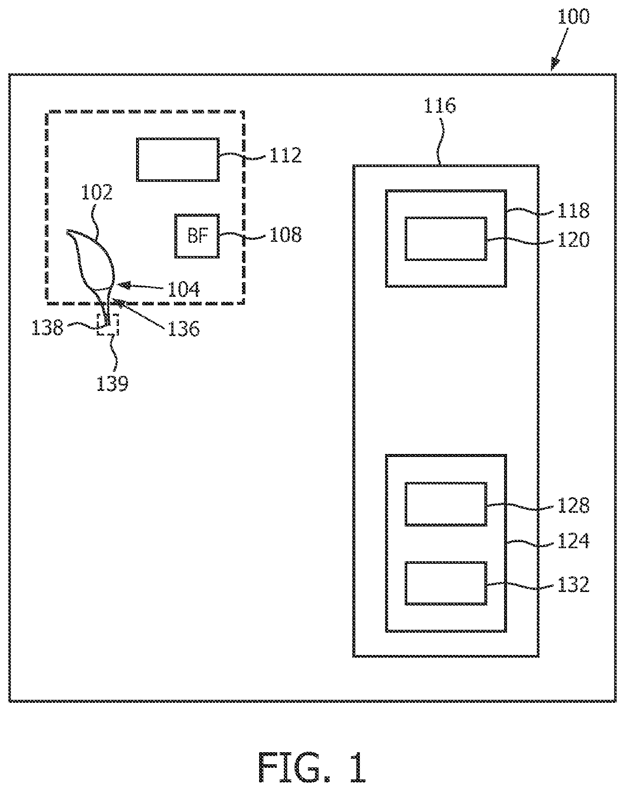
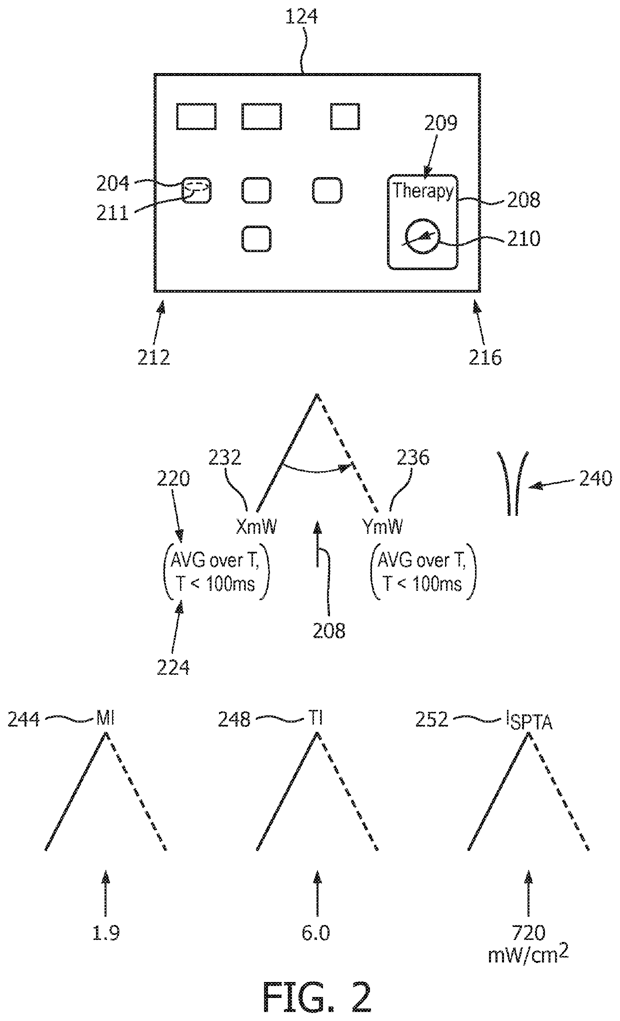
lass="d_n">[0024]FIG. 1 depicts, by way of illustrative and non-limitative example, an ultrasound scanner 100 which incorporates a therapy specific ultrasound shear-wave-elastography exposure-safety facility. In effect, the facility is implementable on a conventional diagnostic ultrasound system. The scanner 100 includes an ultrasound imaging probe 102 that incorporates an ultrasound transducer 104, an ultrasound beamformer 108, an ultrasound exposure safety processor 112, and a user interface 116. The user interface 116 includes a display 118 having a screen 120, and a user control section 124 that includes a facility enablement switch 128 and a fingerprint scanner 132.

[0025]The transducer 104 is configured for conventional ultrasound imaging modes, e.g., A-mode, two-dimensional (or “B-mode”) imaging, Doppler, contrast imaging and etc. It is further configured for producing, i.e., forming and emitting, acoustic-radiation-force-based push pulses 136 for shear wave elastography imagi...


PUM


Abstract

An ultrasound exposure safety processor is configured for spatially relating respective definitions of an imaging zone, and an extended dead-tissue zone that includes both a dead-tissue zone and a surrounding margin. Based on whether a push pulse focus is to be within the extended dead-tissue zone, the processor automatically decides a level of acoustic power with which the pulse is to be produced. If the pulse focus is to be within the extended dead-tissue zone, the pulse may be produced with a mechanical index (MI), a thermal index (TI), and / or a spatial-peak-temporal-average intensity (IspTA) that exceeds respectively 1.9, 6.0 and 720 milliwatts per square centimeter. The imaging zone may be definable interactively to dynamically trigger the deciding and the producing, with push pulse settings being dynamically derived automatically. A display of multiple push pulse sites allows user manipulation of spatial definition indicia to dynamically control displacement tracking.

Description

[0001]This application is the U.S. National Phase application under 35 U.S.C. §371 of International Application No. PCT / IB2015 / 054498, filed on Jun. 15, 2015, which claims the benefit of U.S. Provisional Application Ser. No. 62 / 019,030, filed Jun. 30, 2014. These applications are hereby incorporated by reference herein.FIELD OF THE INVENTION[0002]The present invention relates to medical ultrasound push pulse generation and, more specifically, to applications that involve dead body-tissue.BACKGROUND OF THE INVENTION[0003]Radio-frequency ablation (RFA) is gaining widespread use in minimally invasive treatment of unresectable malignant hepatic tumors. The clinical problem associated with RFA procedures is the high local recurrence rate in treated patients: ranging from 1.7% to 41% for hepatocellular carcinoma. A primary reason is that inaccurate identification of the ablation zone, especially errors in size measurement, leads to undertreatment. The standard of success by which ablation...

Claims


Application Information

Patent Timeline
Patent Type & Authority Patents(United States)
IPC IPC(8): A61B8/08A61B8/00A61B18/14A61B18/00
CPCA61B8/485A61B8/085A61B8/465A61B8/54A61B18/14A61B2018/0066A61B2018/00351A61B2018/00529A61B2018/00547A61B2018/00577A61B2018/00738A61B2018/00994
Inventor XIE, HUAZHOU, SHIWEIROBERT, JEAN-LUCSHAMDASANI, VIJAY THAKURHUANG, SHENG-WEN
Owner KONINKLJIJKE PHILIPS NV
Why Eureka
Try Eureka