Substrate processing apparatus and substrate processing method

Active Publication Date: 2021-12-28
DAINIPPON SCREEN MTG CO LTD
View PDF39 Cites 0 Cited by
  • Summary
  • Abstract
  • Description
  • Claims
  • Application Information

AI Technical Summary

Benefits of technology

[0009]The present invention is intended for a substrate processing apparatus for processing a substrate, and it is an object of the present invention to dissip

Problems solved by technology

If the lower surface of the shielding plate becomes charged, there is a possibility that particles in the atmosphere may be adsorbed to the lower surface of the shielding plate, and the adsorbed particles may drop on a substrate that has undergone dry processing and thereby foul the substrate that has undergone dry processing.
There is also a possibility that discharges between the shielding plate and the substrate may cause damage to wiring on the substrate.
Moreover, for example, the use of combustible chemical solutions as processing liquids may be restricted during the processing of substrates.
The substrate processing apparatus of Pat

Method used


Image

  • Substrate processing apparatus and substrate processing method
  • Substrate processing apparatus and substrate processing method
  • Substrate processing apparatus and substrate processing method

Examples


Embodiment Construction

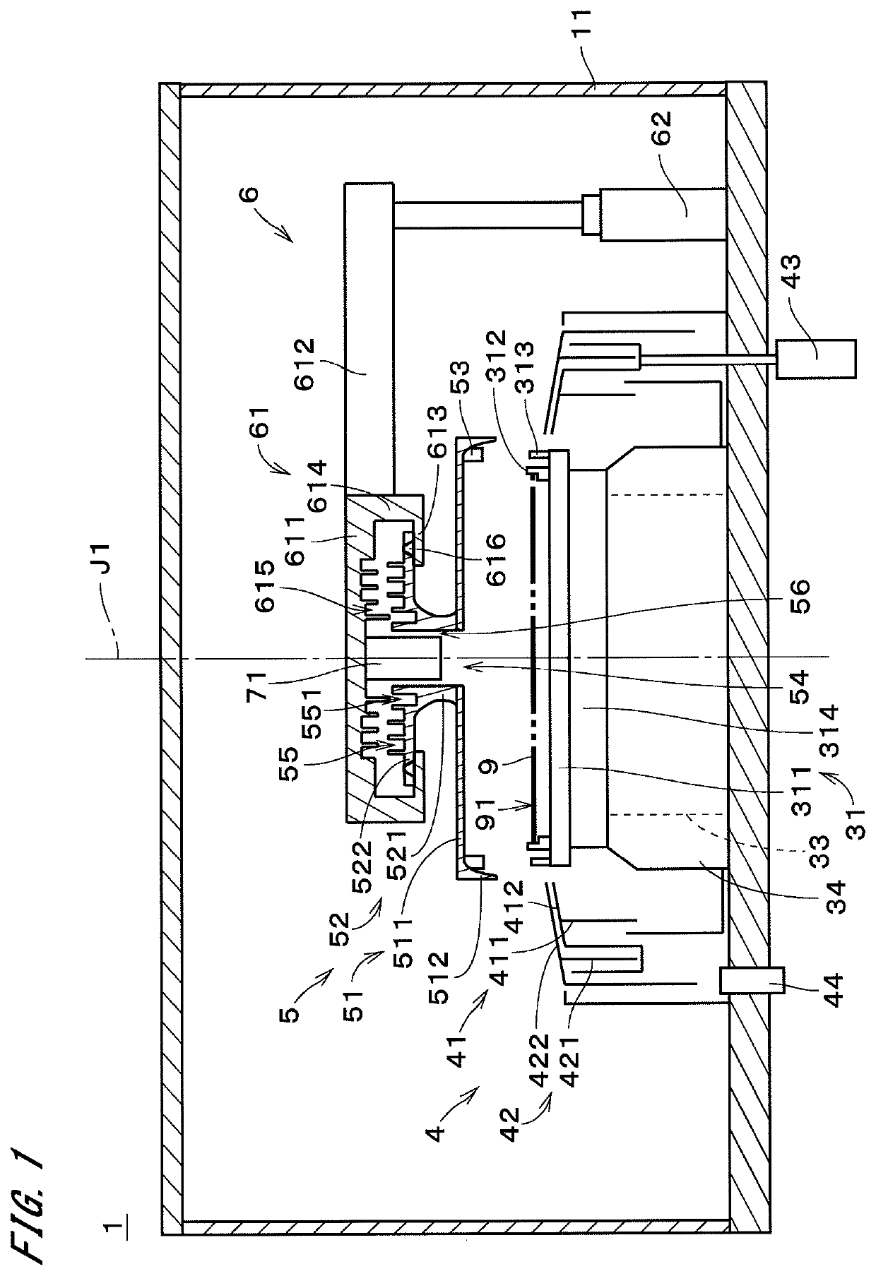
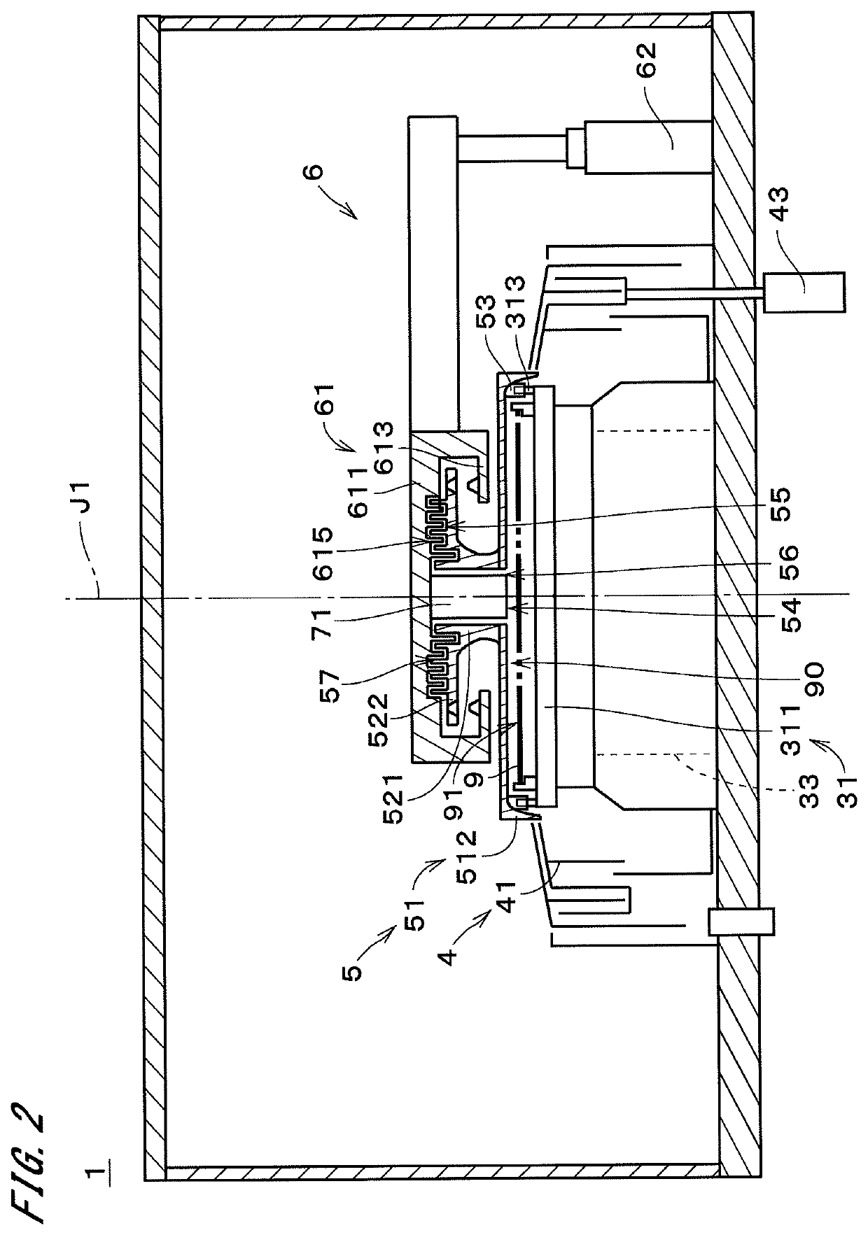
[0029]FIG. 1 is a sectional view of a configuration of a substrate processing apparatus 1 according to an embodiment of the present invention. The substrate processing apparatus 1 is a single wafer processing apparatus for processing semiconductor substrates 9 (hereinafter, simply referred to as “substrates 9”) one at a time. The substrate processing apparatus 1 includes a substrate holder 31, a substrate rotation mechanism 33, a cup part 4, a top plate 5, an opposing-member moving mechanism 6, and a processing liquid nozzle 71. The constituent elements of the substrate processing apparatus 1 are housed inside a housing 11.

[0030]The substrate holder 31 holds a substrate 9 in a horizontal position. The substrate holder 31 includes a holder base 311, a plurality of chucks 312, a plurality of engagement parts 313, and a base supporter 314. The substrate 9 is disposed above and spaced from the holder base 311. The holder base 311 and the base supporter 314 are each a generally disk-like...


PUM


Abstract

A substrate rotation mechanism rotates the substrate holder about a central axis. A top plate opposes the upper surface of the substrate and rotates about the central axis. A gas supply part supplies a treatment atmospheric gas to a radial central part of a lower space that is a space below the top plate. An ion generator generates and supplies ions to the treatment atmospheric gas supplied from the gas supply part. Then, in a state in which the top plate is positioned lower than when the substrate is transported into the apparatus, the treatment atmospheric gas that contains the ions is supplied to the lower space to form an ion stream that spreads radially outward from the radial central part of the lower space while rotating the substrate holder and the top plate. Accordingly, charges can be dissipated from the top plate with a simple structure.

Description

CROSS-REFERENCE TO RELATED APPLICATIONS[0001]The present application is a 35 U.S.C. §§ 371 national phase conversion of PCT / JP2016 / 088671, filed Dec. 26, 2016, which claims priority to Japanese Patent Application No. 2016-022449, filed Feb. 9, 2016, the contents of both of which are incorporated herein by reference. The PCT International Application was published in the Japanese language.TECHNICAL FIELD[0002]The present invention relates to a technique for processing a substrate.BACKGROUND ART[0003]A process of manufacturing a semiconductor substrate (hereinafter, simply referred to as a “substrate”) conventionally involves various types of processing that is performed on the substrate. For example, a chemical solution is supplied to a substrate having a resist pattern on its surface so that chemical solution processing such as etching is performed on the surface of the substrate. After completion of the chemical solution processing, cleaning processing is performed by supplying a c...

Claims


Application Information

Patent Timeline
IPC IPC(8): H01L21/67H01L21/02H01L21/311
CPCH01L21/67034H01L21/0206H01L21/31133H01L21/6708H01L21/67028H01L21/02052H01L21/02307H01L21/67017H01L21/67213H01L21/67259H01L21/68764
Inventor IWAO, MICHINORIMURAMOTO, RYO
Owner DAINIPPON SCREEN MTG CO LTD
Why Eureka
Try Eureka