Stripping of a dip-moulded glove from a former

a technology of dipmoulding former and elastomeric gloves, which is applied in the field of apparatus and method for stripping elastomeric gloves from dipmoulding former, can solve the problems of increasing the cost of labor, the uneven stack of gloves formed under the rollers, and the labour required at the stripping station, so as to reduce the variation in the position of each deposited glove, facilitate the subsequent processing of gloves, and facilitate the effect of deposited gloves

Active Publication Date: 2022-01-04
SAFEDON
View PDF26 Cites 0 Cited by
  • Summary
  • Abstract
  • Description
  • Claims
  • Application Information

AI Technical Summary

Benefits of technology

[0092]It is a particular advantage of the invention that this position can be the result of a natural process in which the beaded end is too large to pass readily through the gap and therefore stops or becomes lodged at the gap. The invention therefore avoids the need for more complicated equipment and ways to achieve this registration, for example using machine vision system of sensors to detect the location of the beaded end.
[0093]Because each glove is held in position with at a well-defined location on the glove, the beaded cuff end, the gloves can then more easily be deposited with a reduced variation in the position of each deposited glove along a longitudinal axis of the glove. This simplifies subsequent processing of the glove and packing into packs, for example for dispensing from box dispensers. Interfolding of gloves by machine for cuff-first dispensing is also simplified. Ultimately, because gloves are packed more uniformly, more gloves can be packed in a box dispenser.
[0094]The invention therefore automatically aligns the beaded end of the stripped glove with respect the first and second gripping members prior to the glove gripper delivering the glove to the next processing stage, with the result that the glove can be delivered to the next processing stage in a predetermined and well-defined physical orientation.

Problems solved by technology

The cost of labour is an increasing component of the total cost of production.
However, the issue is not just the labour required at the stripping station, but also the labour needed to handle gloves after these are removed from the stripping station for packing into boxes or dispensers.
A limitation of machines such as this is that the stack of gloves which is formed beneath the pair of rollers is very uneven.
Although workers can be employed to tidy and align each stack of gloves produced by the machine, the gloves still do not lie evenly flat within the stack, which makes further processing and packing that much more difficult to implement.
The unevenness also significantly limits the maximum number of gloves that can be packaged in a glove dispenser.
Whilst this system is effective in providing a mechanised process for stripping gloves and then depositing gloves on a conveyor belt, the apparatus is relatively complex and heavy, which makes it more difficult to achieve a cycle time fast enough to match the speed of the glove production line.

Method used


Image

  • Stripping of a dip-moulded glove from a former
  • Stripping of a dip-moulded glove from a former
  • Stripping of a dip-moulded glove from a former

Examples


first embodiment

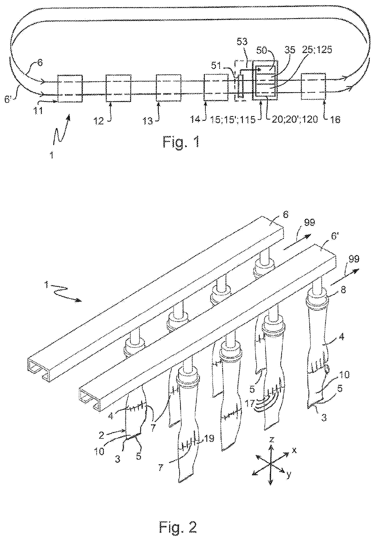
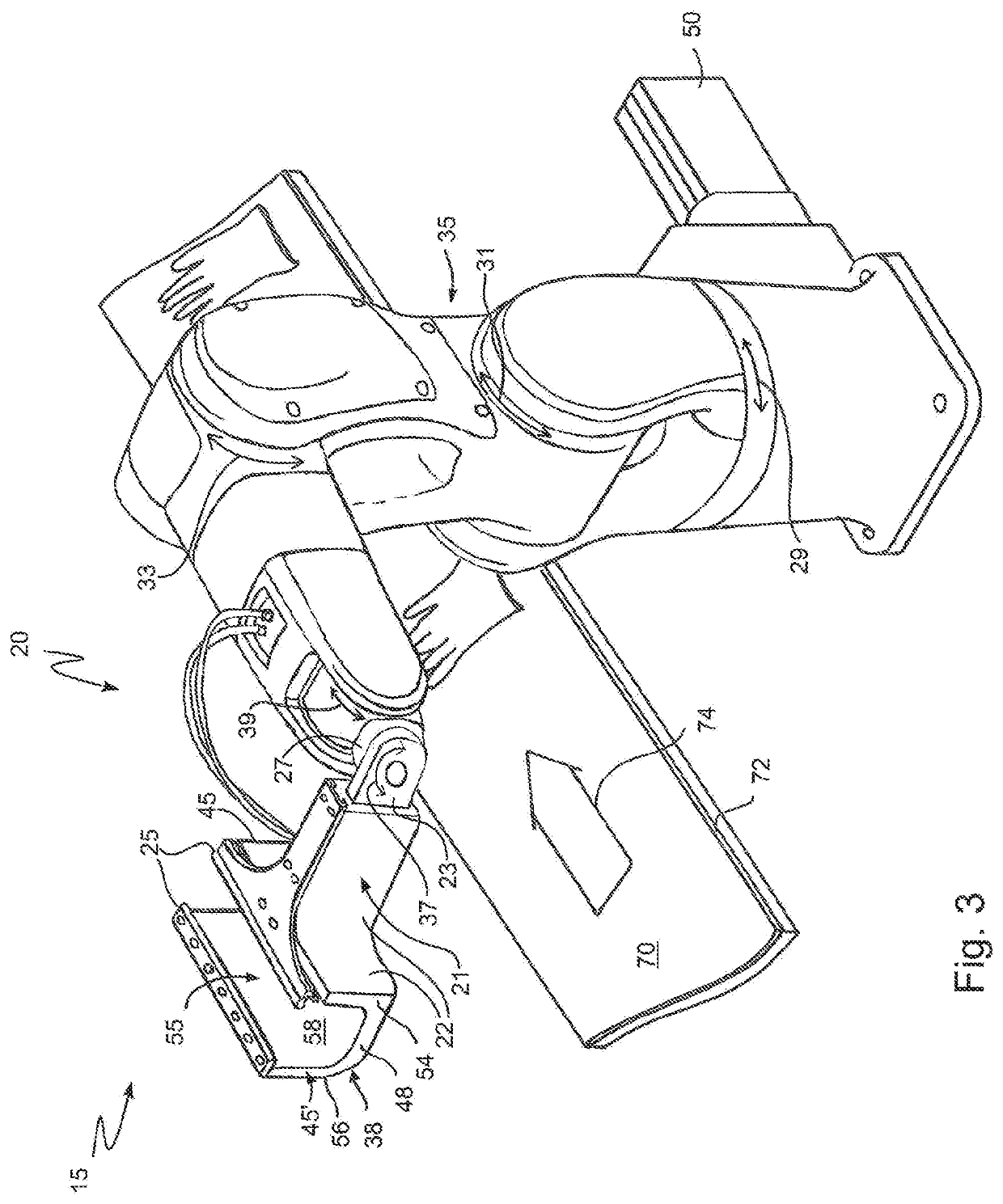
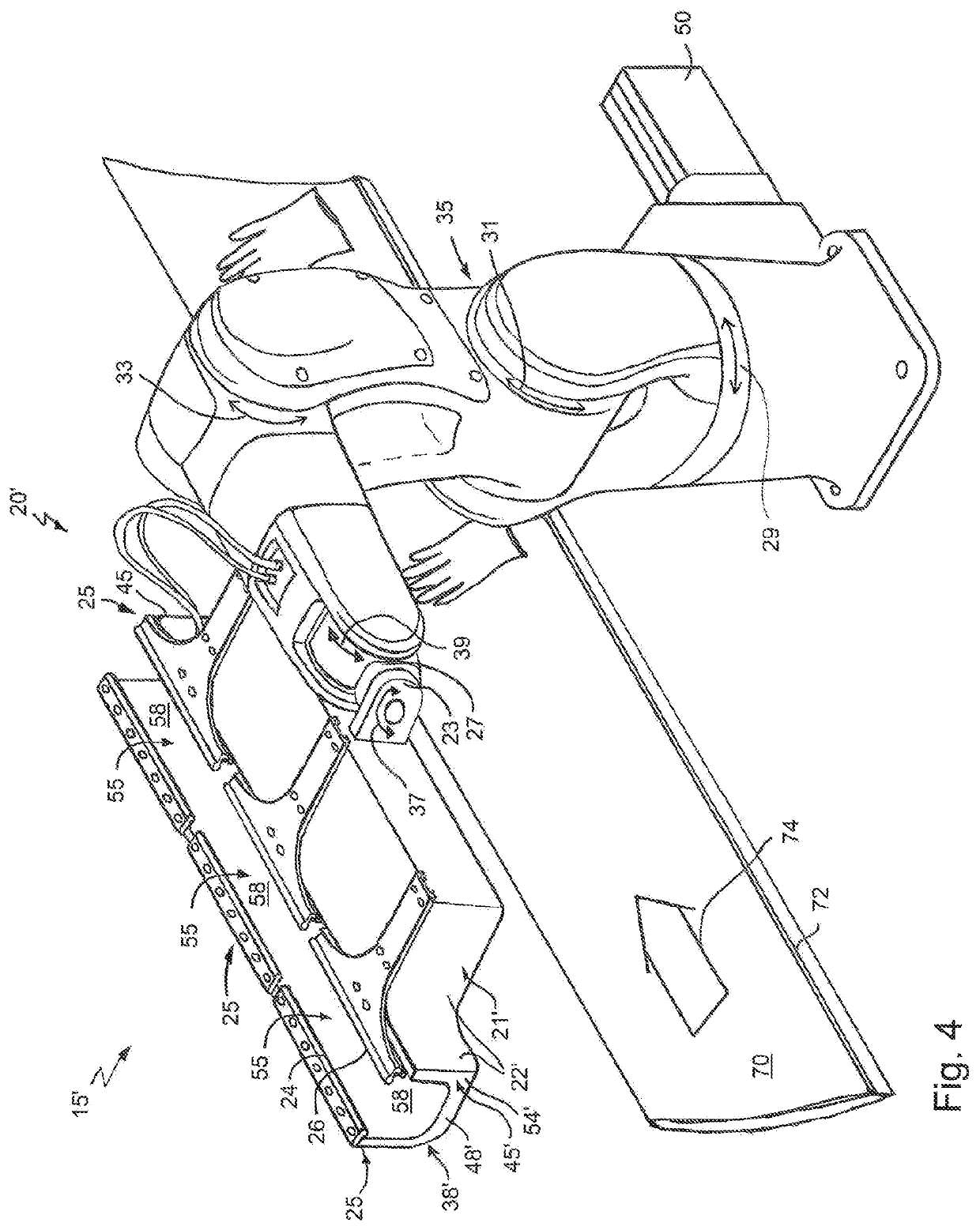
[0126]FIGS. 3 and 4 show two variants of the invention in which a full glove stripping station or stage 15, 15′ has a glove stripping apparatus 20, 20′ with, respectively, one or three gripping devices 25 for fully stripping a partially stripped gloves 2 from the dip-moulding formers. The construction of the gripping device 25 and operation of the first variant of glove stripping station is shown in more detail in FIGS. 5 to 12. As will be explain below, each gripping device comprises a glove gripping actuator.

second embodiment

[0127]FIGS. 13 and 14 show another form of gripping device 125 in the invention, the operation of which as part of a full glove stripping station or stage 115 is shown in more detail in FIGS. 15 to 19.

[0128]Both embodiments include a robotic arm 35, which provides a glove stripping actuator, and an associated controller 50 for synchronised control of the movement of both the robotic arm and gripping device 25, 125.

[0129]There are limits to the speed of movement of the robotic arm and gripping device 25, 125, and therefore, for the sake of efficiency, each robotic and associated gripping device 25, 125 is preferably configured to strip gloves 2 from just one of the two dip-moulding production line tracks 6, 6′, rather than from both. Furthermore, there may be more than one robotic arm and associated gripping device for each production line track. For example, the robotic arm 35 with one gripping device 25, 125 is capable of stripping and depositing one glove every 1.8 s. Current prod...


PUM

PropertyMeasurementUnit
widthaaaaaaaaaa
widthaaaaaaaaaa
widthaaaaaaaaaa

Abstract

A glove stripping apparatus (15) for fully stripping a partially stripped elastomeric dip-moulded glove (2) from a hand-shaped dip-moulding former (4) comprises a gripping device (25) relatively movable with respect to a downwardly hanging cuff end portion (10), a gripping actuator (32), a stripping actuator (35) and a controller for controlling the operation of the actuators. The relative movement of the gripping device and the downwardly hanging cuff end portion is driven by the stripping actuator. The gripping device has first and second gripping members (24, 26) movable relative to each other by the gripping actuator. The gripping members provide opposed gripping surfaces (34, 36) for gripping the cuff end portion. The first gripping member and the second gripping member initially provide a horizontally extending gap between the gripping surfaces which receives the cuff end portion. The gripping members are moved to reduce the gap (40′) until the cuff end portion is restrained between the gripping surfaces with a beaded cuff end (3) of the glove being below the gap. The gripping members are moved downwardly (46) together towards the beaded cuff end so that the cuff end portion moves upwards relative to the gap until the beaded cuff end (3) is caught by the gap (40′). The downward movement is then continued until the glove is fully stripped from the dip-moulding former.

Description

BACKGROUNDa. Field of the Invention[0001]The present invention relates to an apparatus and method for the stripping of elastomeric gloves from a dip-moulding former, when the gloves have already been partially stripped such that each glove has a downwardly hanging cuff end portion with a terminal beaded cuff end. The invention particularly relates to the stripping and subsequent handling of dip-moulded disposable inspection gloves such as those used in clinical, veterinary, dental or medical environments or in other situations where hygiene is important, such as food preparation.b. Related Art[0002]There is an increasing need to control infection of patients in hospitals, clinics, and doctors' surgeries from infectious bacteria resistant to multiple antibiotics, in particular methicillin-resistant Staphylococcus aureus (MRSA). Research has also shown that if someone has MRSA on their hands, the bacteria would be left on the next four surfaces touched by that person. Once MRSA is on ...

Claims


Application Information

Patent Timeline
Patent Type & Authority Patents(United States)
IPC IPC(8): B29C41/42B29C41/14B25J11/00B29C37/00B29L31/48B29D99/00B29K21/00
CPCB29C41/42B25J11/00B29C37/0017B29C41/14B29D99/0067B29K2021/00B29L2031/4864
Inventor STOLLERY, JONATHAN WILLIAMSTOLLERY, KIM MARIE
Owner SAFEDON
Why Eureka
Try Eureka