Diagnostic method and device for checking the functionality of a component for exhaust-gas aftertreatment

Active Publication Date: 2022-02-01
VOLKSWAGEN AG
View PDF34 Cites 0 Cited by
  • Summary
  • Abstract
  • Description
  • Claims
  • Application Information

AI Technical Summary

Benefits of technology

[0028]In a preferred embodiment of the invention, it is provided for the secondary air supply source to comprise an electrically powered secondary air pump. An electrically commutated secondary air pump offers the advantage that the secondary air pump can be switched on and off as needed. Consequently, the additional energy demand for the secondary air can be kept low and a sufficient volume of secondary air can be introduced into the exhaust gas channel for diagnostic purposes. Moreover, the secondary air pump can be utilized to assist in the regeneration of the particulate filter.
[0029]According to an advantageous refinement of the invention, it is provided for a first lambda sensor to be arranged downstream from the opening and upstream from the particulate filter, and for a second lambda sensor to be arranged in the exhaust gas channel downstream from the particulate filter. Since one lambda sensor is arranged upstream from the particulate filter and another lambda sensor is arranged downstream from the particulate filter, the oxygen content of the exhaust gas can be determined upstream and downstream from the particulate filter. This makes it particularly easy to determine the oxygen storage capacity of the particulate filter.
[0030]In another improvement of the invention, it is provided for the particulate filter to be positioned far away from the engine, preferably in the undercarriage of a motor vehicle. In this context, the term “far away from the engine” refers to a position having an exhaust gas travel path of at least 80 cm, preferably at least 100 cm, beyond the e

Problems solved by technology

This can mean that a gasoline particulate filter has to be used in some models.
This is done especially when, due to low exhaust gas volumes and a low exhaust gas fl

Method used


Image

  • Diagnostic method and device for checking the functionality of a component for exhaust-gas aftertreatment
  • Diagnostic method and device for checking the functionality of a component for exhaust-gas aftertreatment
  • Diagnostic method and device for checking the functionality of a component for exhaust-gas aftertreatment

Examples


Embodiment Construction

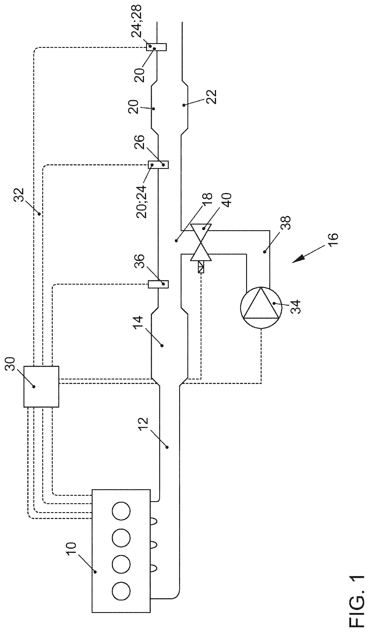
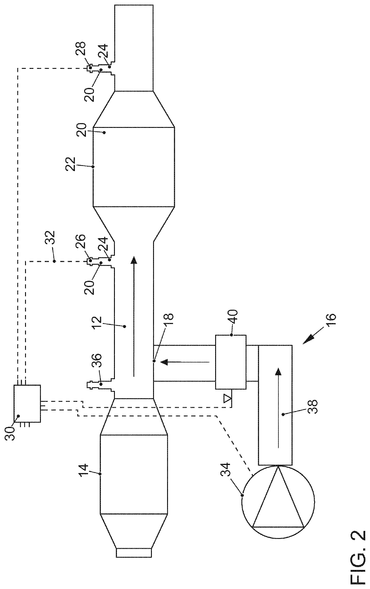
[0038]FIG. 1 shows an internal combustion engine 10 for a motor vehicle, comprising an exhaust gas channel 12 as well as a three-way catalytic converter 14 arranged in the exhaust gas channel 12. The internal combustion engine 10 is preferably configured as an externally ignited internal combustion engine 10 operating according to the Otto principle. Downstream from the three-way catalytic converter 14 as seen the flow direction of the exhaust gas, there is an opening 18 where secondary air can be introduced into the exhaust gas channel 12 of the internal combustion engine 10 by means of a secondary air supply source 16. Downstream from the opening 18, there are additional components 20 for the exhaust-gas aftertreatment, especially a particulate filter 22 with a three-way catalytically active coating, as well as lambda sensors 26, 28 that regulate the oxygen content in the exhaust gas channel 12 of the internal combustion engine 10. The lambda sensors 26, 28 are connected via signa...


PUM


Abstract

The invention relates to a diagnostic method for checking the functionality of a component for the exhaust-gas aftertreatment of an internal combustion engine. For this purpose, in an internal combustion engine, a secondary air supply is provided by means of which an excess of oxygen can be generated in the exhaust gas channel essentially independently of the operating conditions of the internal combustion engine, and wherein said excess of oxygen is utilized for the measurement of an oxygen storage capacity of the component or of a signal change at the component. It is provided that the component is subsequently subjected to a substoichiometric exhaust gas in order that the oxygen release capacity or the signal change upon a change from superstoichiometric exhaust gas to a substoichiometric exhaust gas is also taken into consideration in the diagnosis. The invention also relates to a device for exhaust-gas aftertreatment, which is designed to be able to carry out a method of said type.

Description

CROSS-REFERENCE TO RELATED APPLICATIONS[0001]This application is a National Phase Application of PCT International Application No. PCT / EP2017 / 070138, International Filing Date Aug. 9, 2017, claiming priority of German Patent Application No. 10 2016 114 901.2, filed Aug. 11, 2016, which is hereby incorporated by reference.FIELD OF THE INVENTION[0002]The invention relates to a diagnostic method for checking the functionality of a component for the exhaust-gas aftertreatment of an internal combustion engine as well as to a device for carrying out such a diagnostic method.BACKGROUND OF THE INVENTION[0003]Since current and future legislation on exhaust gas emissions is becoming increasingly stringent, high requirements are being made when it comes to the raw engine emissions and the exhaust-gas aftertreatment of internal combustion engines. The introduction of the next European emission standard Euro 6 for gasoline engines stipulates a limit value for the number of particles. This can me...

Claims


Application Information

Patent Timeline
IPC IPC(8): F01N3/00F01N11/00F01N3/035F01N3/10F01N3/32
CPCF01N11/007F01N3/035F01N3/101F01N3/323F01N2430/06F01N2900/1624F01N3/30F01N9/00F01N11/00F01N3/021F01N2550/00F01N2550/02F01N2560/025F01N2560/14F01N2900/1622Y02T10/12Y02T10/40
Inventor RIECHERT, CHRISTIANWITTIG, FRANK-MICHAEL
Owner VOLKSWAGEN AG
Why Eureka
Try Eureka