
Veneer dehydration method and veneer dehydration system

a dehydration system and veneer technology, applied in the direction of veneer presses, drying machines with progressive movements, lighting and heating apparatus, etc., can solve the problems of cracks in such veneers in the fiber direction, complicated control, and enlarged devices, and achieves favorable effect, high tensile strength, and simple configuration of anisotropy

Active Publication Date: 2022-02-15
MEINAN MASCH WORKS INC
View PDF7 Cites 0 Cited by
  • Summary
  • Abstract
  • Description
  • Claims
  • Application Information

AI Technical Summary

Benefits of technology

[0006]The invention was contrived in view of the foregoing circumstances, and an object thereof is to provide a veneer dehydration method and a veneer dehydration system which, while simply constructed, are capable of not only restricting a veneer from stretching in the direction intersecting with the fiber direction of the veneer, but also reducing cracking of the veneer attributed to such stretching.
[0028]The invention, while simply constructed, is capable of not only restricting a veneer from stretching in a direction intersecting with a fiber direction of the veneer or in a direction in which lathe checks of the veneer expand, but also reducing cracking of the veneer attributed to such stretching.

Problems solved by technology

However, the veneer dehydration method described above needs to operate the pair of restricting members along with a conveyor carrying the layered-up veneer board and the upper and lower platens, making the control complicated.
Furthermore, a mechanism for operating the pair of restricting members is required in addition to the pair of restricting members, resulting in a complicated, enlarged device.
If the plurality of veneers constituting the layered-up veneer board have non-uniform dimensions in the fiber intersecting directions, some of these veneers would not be restricted by the pair of restricting members from stretching in the fiber intersecting directions, resulting in cracks in such veneers in the fiber directions thereof.
Even when the dimensions of the plurality of veneers are uniform in the fiber intersecting directions, as long as there exist veneers with lathe checks (cracking caused due to the difference in dimensions between the inner and outer peripheries of a veneer when a rotary lathe thinly cuts a log into a veneer and deforms the resultant veneer into a flat shape), the pair of restricting members cannot restrict such veneers from stretching in the fiber intersecting directions, resulting in cracks in the veneers in the fiber directions.

Method used


Image

  • Veneer dehydration method and veneer dehydration system
  • Veneer dehydration method and veneer dehydration system
  • Veneer dehydration method and veneer dehydration system

Examples


example 1

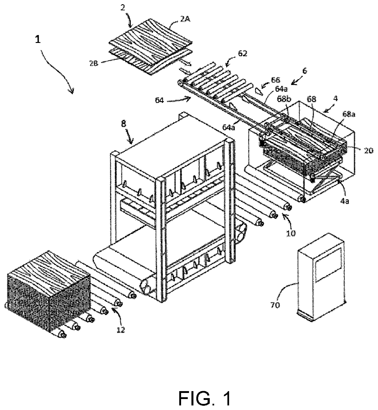
[0054]As shown in FIG. 1, a veneer dehydration system 1 according to an embodiment of the invention includes a veneer stacking device 4 capable of stacking veneers 2 into layers, a conveying device 6 for conveying veneers 2 to the veneer stacking device 4, a compression device 8 for compressing the layered veneers 2 (“layered-up veneer board 20,” hereinafter) in a layering direction, a loading device 10 for loading the layered-up veneer board 20 of the veneer stacking device 4 onto the compression device 8, an unloading device 12 for unloading the layered-up veneer board 20 from the compression device 8, and a controller 70 for controlling the entire system.

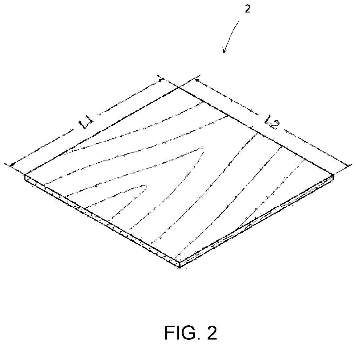
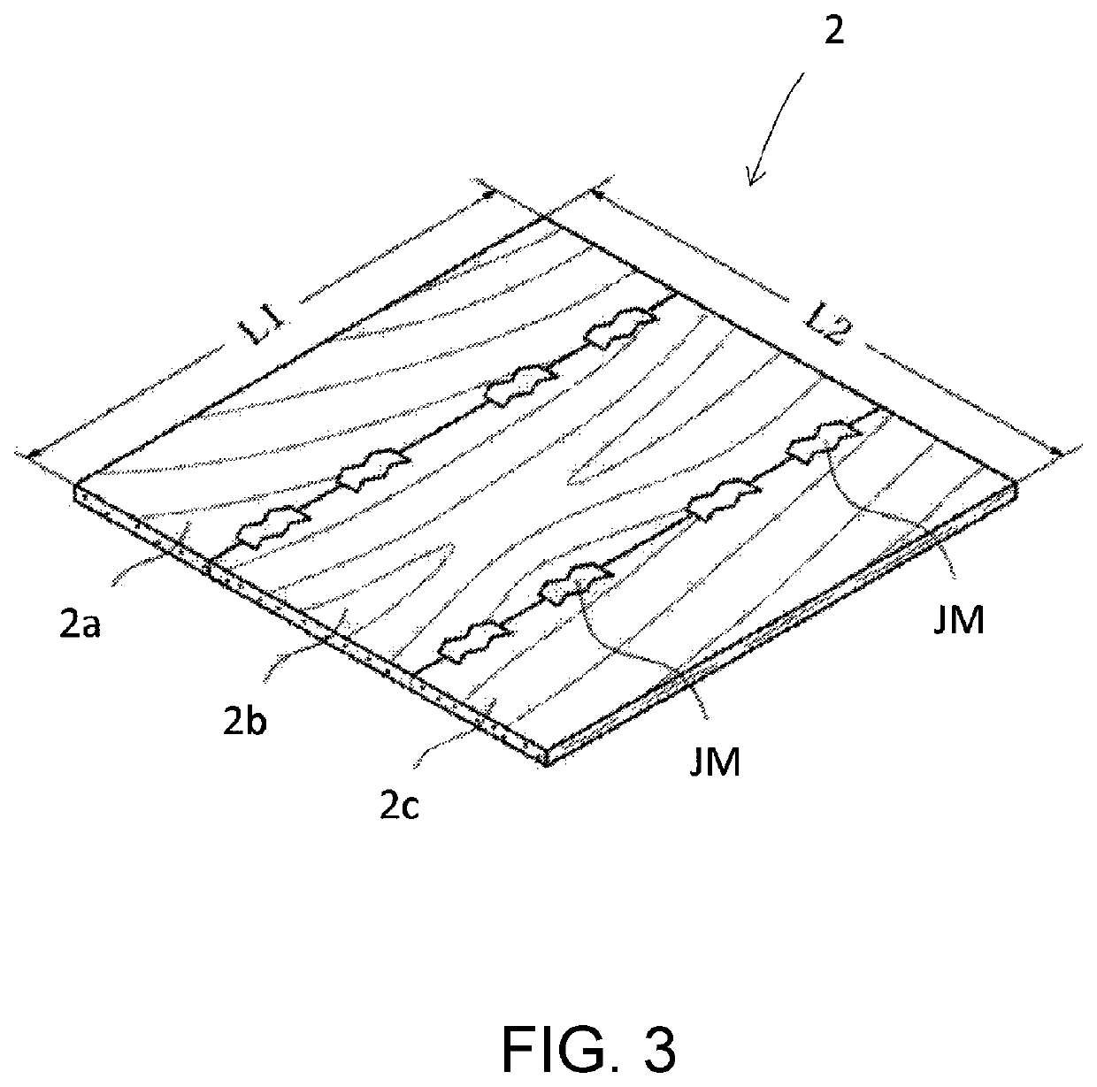
[0055]A veneer 2 is obtained by thinly cutting a log using a veneer lathe, not shown. In this embodiment, as shown in FIGS. 2 to 4, the veneer 2 is in a square shape when viewed from the direction perpendicular to a primary surface of the veneer 2 (the length of the veneer 2 along a fiber direction thereof is roughly equal to the...


PUM

PropertyMeasurementUnit
heightaaaaaaaaaa
heightaaaaaaaaaa
stressaaaaaaaaaa

Abstract

A layered-up veneer board is formed by layering veneers up to a predetermined height such that the fiber directions of the respective veneers are alternately perpendicular to one another, and the layered-up veneer board is compressed by a compression device, to remove moisture contained in the veneers. Wood is a material in which the tensile strength in the fiber direction of the wood is higher than the tensile strength in the direction perpendicular to the fiber direction. With this layering scheme, even when stress is applied to the veneers and causes elongational deformation of these veneers as a result of compressing the layered-up veneer boards in the layering direction, elongational deformation of the veneers in the directions perpendicular to the fiber directions thereof can be reduced.

Description

CROSS-REFERENCE TO RELATED APPLICATIONS[0001]This application claims priority to Japanese Patent Application No. 2018-137257, filed Jul. 20, 2018. The contents of that application are incorporated by reference herein in their entirety.BACKGROUND1. Field of the Invention[0002]The invention relates to a veneer dehydration method and a veneer dehydration system for removing moisture contained in veneers.2. Description of the Related Art[0003]Japanese Patent Application No. 4783862 discloses a veneer dehydration method. In this veneer dehydration method, a layered-up veneer board, which is obtained by layering a plurality of veneers for plywood one above the other with the fiber directions thereof aligned, is loaded between a pair of upper and lower platens arranged facing each other, and then, of the side wall surfaces of the loaded layered-up veneer board, a pair of side wall surfaces extending along the fiber directions of the veneers is held by the restricting members which are inst...

Claims


Application Information

Patent Timeline
Patent Type & Authority Patents(United States)
IPC IPC(8): B27D1/04F26B5/14B27D3/02
CPCB27D1/04B27D3/02F26B5/14F26B2210/14F26B15/12F26B25/004
Inventor SUZUKI, SHUNICHIHATTORI, YUKIO
Owner MEINAN MASCH WORKS INC
Learn More