
Digital microfluidic devices and methods

a microfluidic device and digital technology, applied in fluid controllers, laboratory glassware, chemistry apparatus and processes, etc., can solve the problems of large manual labor, large droplets to collect enough analyte for further manipulation, and high labor intensity

Active Publication Date: 2022-02-22
MIROCULUS
View PDF336 Cites 2 Cited by
  • Summary
  • Abstract
  • Description
  • Claims
  • Application Information

AI Technical Summary

Benefits of technology

The patent describes methods and devices for handling and analyzing samples of fluid, particularly large samples. The methods and devices involve manipulating small droplets of fluid using digital microfluidics (DMF) devices. The apparatuses can be used for various applications such as extracting analytes from samples or performing other analytical procedures. The apparatuses have a unique design that allows for efficient handling of samples and can be used with other devices such as fluid application and extraction devices. The technical effects of the patent include improved methods and devices for handling and analyzing samples of fluid, particularly large samples, which can be useful in various fields such as laboratory, biological, or chemical research.

Problems solved by technology

However, a continuing challenge for DMF is handling of “real-world” samples, which typically comprise fluid volumes greater than ones easily accommodated by DMF devices, containing analytes of interest at concentrations too dilute to support downstream processing and detection without prior concentration.
Some groups have demonstrated that droplets can be dispensed onto DMF devices from large volumes (hundreds of microliters to milliliters) contained in off-device reservoirs; this only partially addresses the challenge, however, because on-device processing of hundreds or thousands of droplets to collect enough analyte for further manipulation is often not a realistic strategy.
However, off-device concentration of sample analytes must be carried out independently for each sample, necessitating considerable manual labor (or a robotic system) and risking contamination of, and worker exposure to, the samples.

Method used


Image

  • Digital microfluidic devices and methods
  • Digital microfluidic devices and methods
  • Digital microfluidic devices and methods

Examples


example 1

Application: miRNA Extraction and Purification

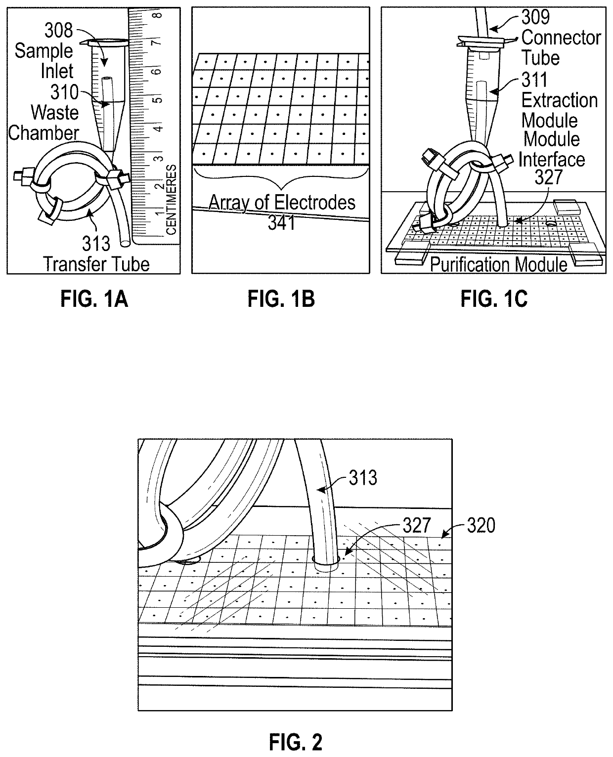
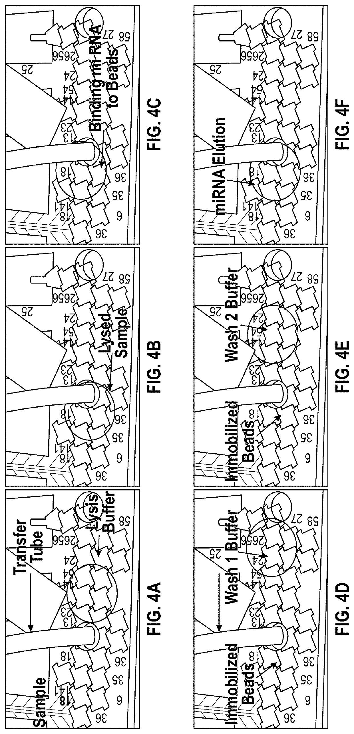
[0081]To evaluate a utility of the system described herein in processing of real-world samples, we tasked it with extraction and purification of miRNA from human plasma, through implementation of TaqMan® miRNA ABC Purification Kit (Thermo Fisher Scientific). As illustrated in FIGS. 4A-4F, a plasma sample (50 μL) was introduced into the system's Purification Module (i.e. DMF platform) from the first tubing (e.g., from sample prep tubing), then sequentially mixed with Lysis Buffer (100 μL) and miRNA Binding Beads (80 μL), in each case aspirating the reagent mixture from the Purification Module into Transfer conduit and then rapidly shuttling the bolus between the two locations to mix thoroughly (frames 1-3). After allowing the beads to bind miRNA in the Lysate (40 min incubation at 35° C.), the reaction mixture (total volume: 150 μL) was exchanged between the Purification Module and Transfer conduit three times while engaging an external m...


PUM


Abstract

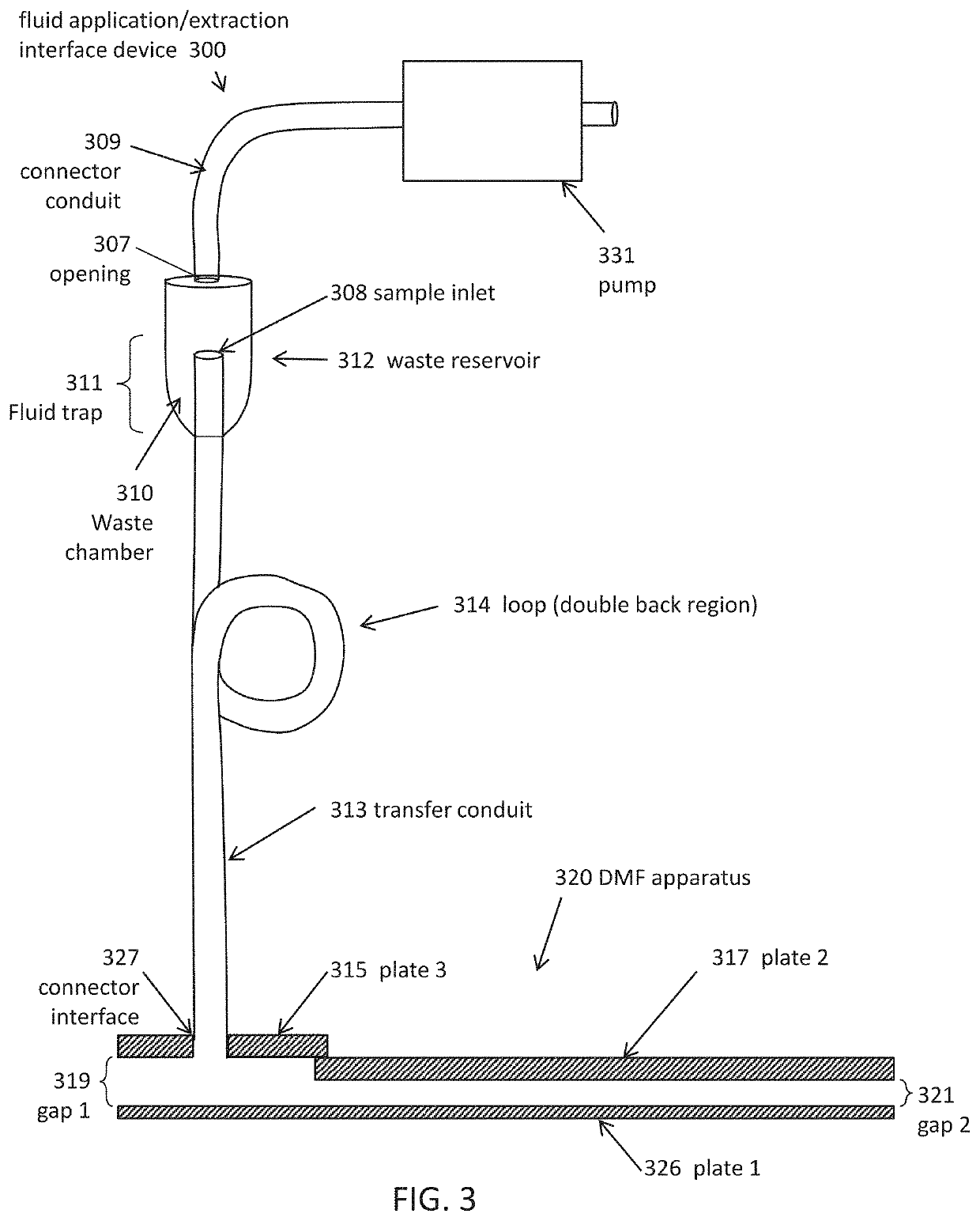
Digital microfluidic (DMF) apparatuses, systems, devices and associated fluid manipulation and extraction devices, and methods of using them are presented. The devices may be useful for analysis of clinical, laboratory, chemical, or biological samples. A fluid application and extraction interface device may include a waste reservoir with a fluid trap and a transfer conduit extending through the waste reservoir so that fluid may pass from the transfer conduit into the waste reservoir and be trapped within the waste chamber. A transfer conduit may be configured to double back on itself and to hold a fluid sample. A DMF apparatus may be configured to hold and process large sample volumes.

Description

CROSS REFERENCE TO RELATED APPLICATIONS[0001]This patent application is a continuation of International Patent Application No. PCT / US2017 / 068839, filed Dec. 28, 2017 and titled “DIGITAL MICROFLUIDIC DEVICES AND METHODS.” This patent application claims priority to U.S. provisional patent application No. 62 / 439,641, filed on Dec. 28, 2016 and titled “DIGITAL MICROFLUIDIC DEVICES AND METHODS”. This patent application also claims priority to U.S. provisional patent application No. 62 / 553,743, filed on Sep. 1, 2017, and titled “DIGITAL MICROFLUIDICS DEVICES AND METHODS OF USING THEM.” This patent application also claims priority to U.S. provisional patent application No. 62 / 557,714, filed on Sep. 12, 2017 and titled “DIGITAL MICROFLUIDICS DEVICES AND METHODS OF USING THEM.” Each of these patent application is herein incorporated by reference in its entirety.INCORPORATION BY REFERENCE[0002]All publications and patent applications mentioned in this specification are herein incorporated by ...

Claims


Application Information

Patent Timeline
Patent Type & Authority Patents(United States)
IPC IPC(8): B01L3/00
CPCB01L3/502792B01L3/50273B01L2200/027B01L2200/16B01L2300/0645B01L2300/0816B01L2300/0883B01L2300/123B01L2300/165B01L2400/0427B01L2400/0487B01L3/502707B01L3/502784B01L7/525G01N1/34B01L2300/161B01L2300/1822B01L2300/1827B01L2400/043B01L3/502715B01L2200/0673B01L2200/0689B01L2300/0819
Inventor JEBRAIL, MAIS J.CHO, ALEXANDRA J.LEE, VICTOR
Owner MIROCULUS
Learn More