
Device for surgically correcting ametropia of an eye and method for creating control data therefor

a technology of ametropia and eye, applied in the field of eye ametropia surgical correction and control data creation, can solve the problems of limited correction options, inapplicability to refractive surgery on the eye, and inability to use the empirical values developed for polishing the eye by laser radiation application, so as to achieve secure and simple volume enclosure

Active Publication Date: 2022-03-15
CARL ZEISS MEDITEC AG
View PDF34 Cites 0 Cited by
  • Summary
  • Abstract
  • Description
  • Claims
  • Application Information

AI Technical Summary

Benefits of technology

[0015]The invention is based on designing the definition of the closed volume within the cornea to be as expedient as possible from an application point of view and, in particular, of obtaining a secure and simple enclosure of the volume.
[0025]The distance between the base edge and the anterior cut surface, i.e., the height of the cylinder or of the conical frustum, optionally comprises a minimum extent. This is provided so that the volume to be removed has a minimum thickness and a certain amount of stability. In this way, damage to the lenticule to be removed can be avoided, said damage possibly leading to residues in the cornea and consequently influencing the refractive error correction.
[0029]The side cut has a non-circular base and top edge and coincides with the oval edge of the posterior cut surface on the base edge. Consequently, there is no transition zone in the posterior cut surface in the case of an oval correction zone for converting the oval edge into a circular edge; instead, the side cut adjoins the edge of the correction zone without a gap. Consequently, less volume is removed from the cornea of the eye since the volume under the transition zones, as used in the prior art, need not be removed. Further, guiding the cut is simplified since there is no need to provide transition zones. Only the posterior cut surface is produced using known procedures and, following this, the side cut is introduced into the cornea. Further, the method can be performed quicker by the omission of the transition zone.
[0030]Moreover, this avoids allowing the actually produced refractive power change to deviate from the calculated refractive power change as a result of the transition zone. Moreover, the computational outlay for producing the posterior cut surfaces can be reduced since methods for producing the transition zones are omitted. Additionally, the technically complex blanking of laser radiation is no longer necessary.
[0034]The configuration of the edge of the posterior cut surface is particularly simple if the plane of the edge is perpendicular to a principal direction of incidence of the laser radiation for producing the cut surfaces. In particular, the plane in which the circumferential line of the anterior cut surface extends is also perpendicular to the principal direction of incidence of the laser radiation. In the case where the side cut is a cylinder, the circumferential surface of the side cut is parallel to the principal direction of incidence.

Problems solved by technology

Empirical values that were developed for polishing the cornea by application of ablation laser radiation are not usable for such methods.
However, this simplification is also accompanied by a certain restriction in the possible correction results because, necessarily, only corrections that would be possible with normal spectacles can be achieved.
This is not applicable in refractive surgery on the cornea since the cornea of the eye naturally also moves when changing the direction of view as a result of the eye movement.
Consequently, the approach known from DE 102006053120 A1 can only use comparatively simple spectacle lens refractive error correction data as input variables for the control data—with the consequence of correspondingly limited correction options.
Firstly, this is not possible in the case of a farsightedness correction since the volume to be removed in that case must be thinner in the center, i.e., in the region of the visual axis, than at the edge.
Since there are also device-related boundary conditions, for example the possible degrees of freedom of the laser beam deflections, and also application-related boundary conditions, such as, for example, regression effects during the healing process, surgical handling of the tissue volume to be removed, maximum tolerable time duration for producing the cut surfaces, etc., the boundary value problem arising overall is by all means complex.

Method used


Image

  • Device for surgically correcting ametropia of an eye and method for creating control data therefor
  • Device for surgically correcting ametropia of an eye and method for creating control data therefor
  • Device for surgically correcting ametropia of an eye and method for creating control data therefor

Examples


Embodiment Construction

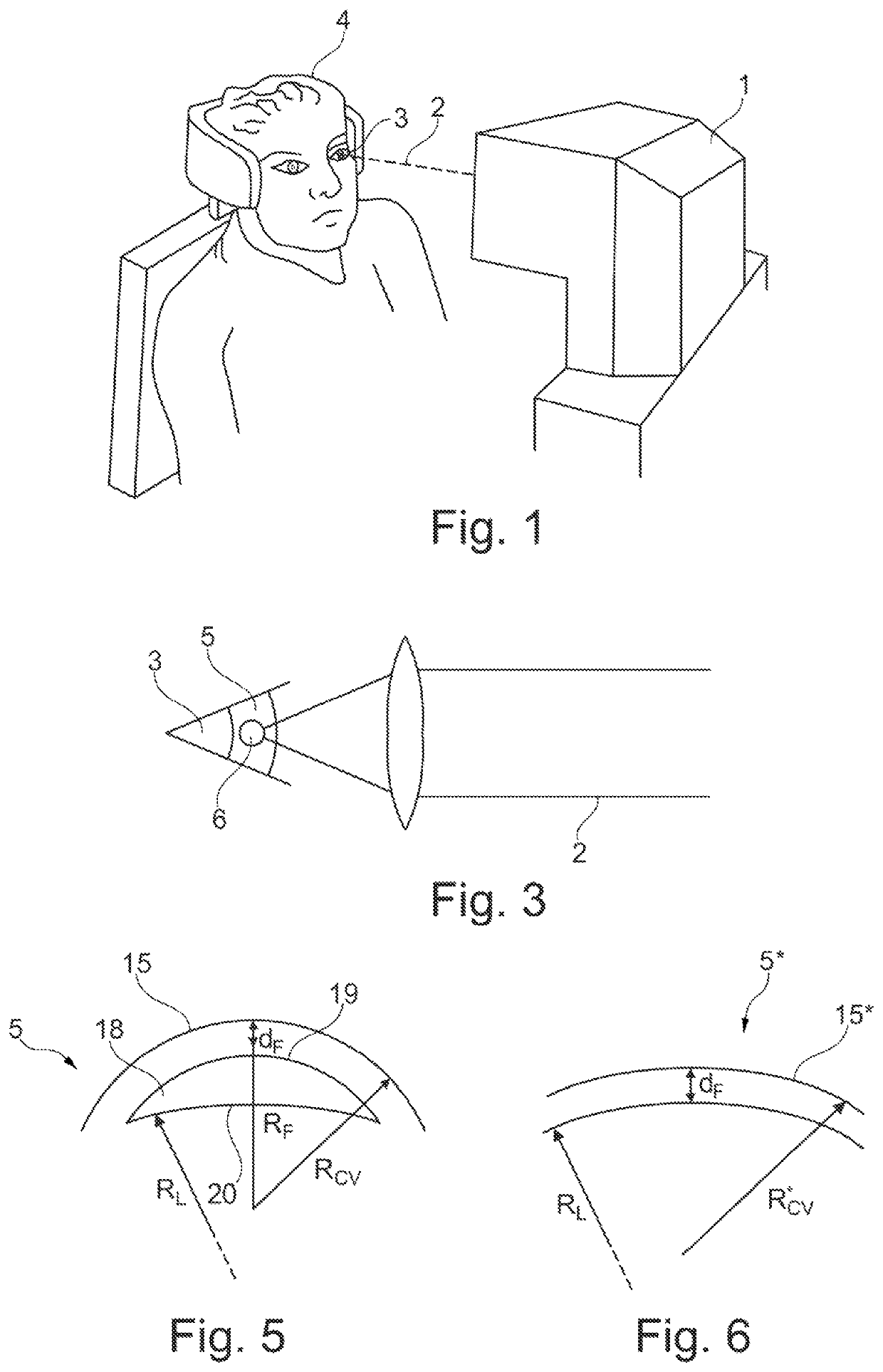
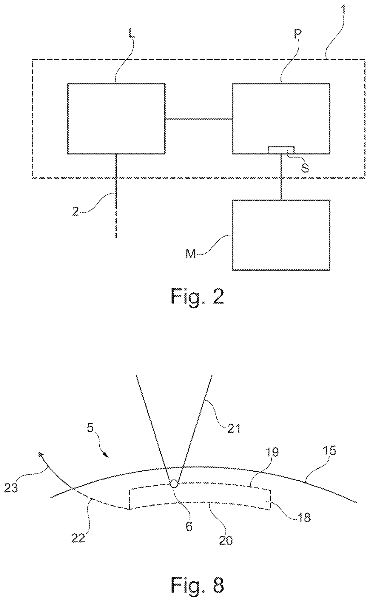
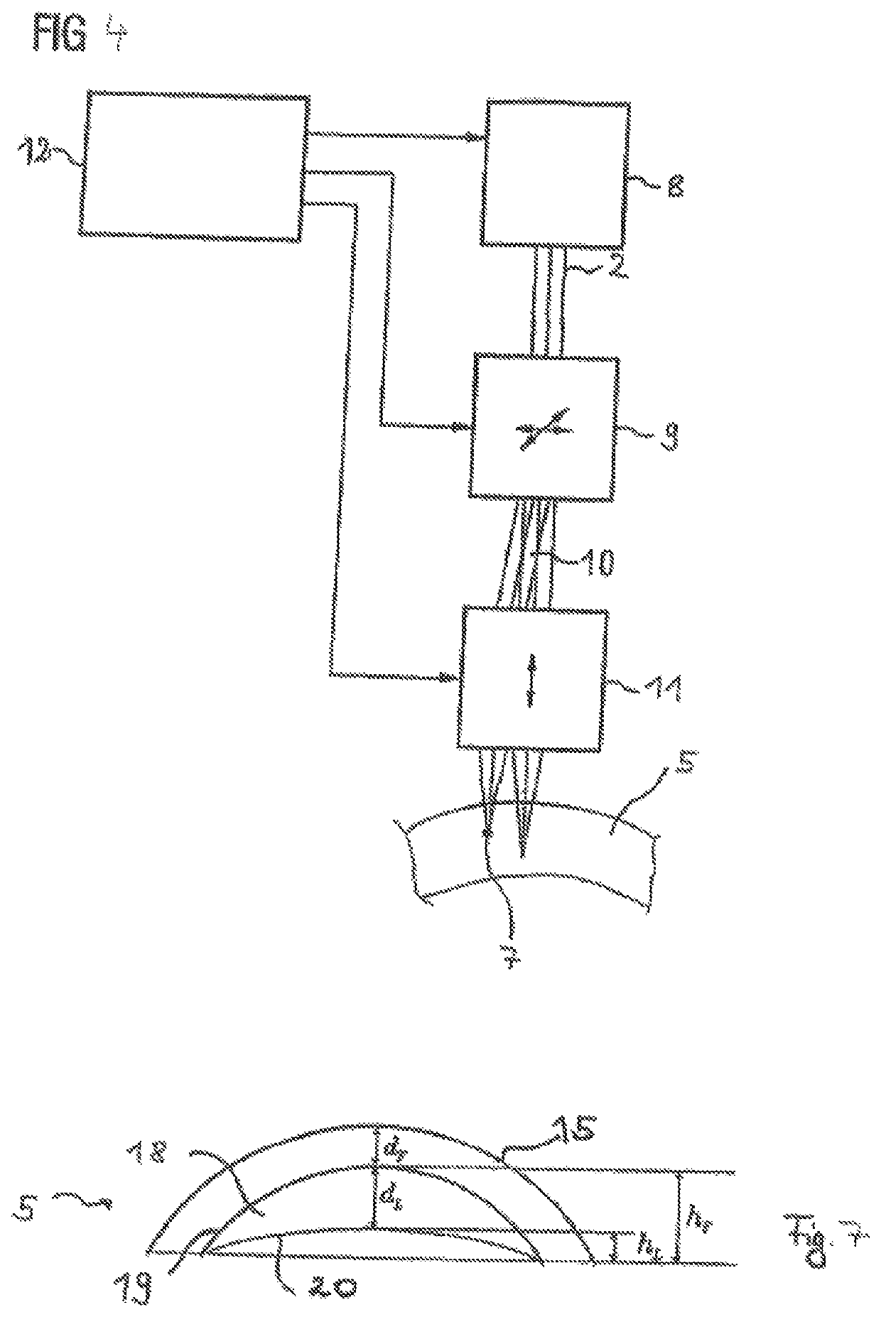
[0057]FIG. 1 depicts a treatment appliance 1 for an ophthalmic surgical method that is similar to the one described in EP 1159986 A1 and U.S. Pat. No. 5,549,632. By application of treatment laser radiation 2, the treatment appliance 1 brings about a refractive error correction on an eye 3 of a patient 4. The refractive error may comprise hyperopia, myopia, presbyopia, astigmatism, mixed astigmatism (astigmatism, in which hyperopia is present in one direction and myopia is present in a direction at right angles thereto), aspherical aberrations and higher-order aberrations. In the described embodiment, the treatment laser radiation 2 is applied as a pulsed laser beam that is focused into the eye 3. Here, the pulse duration lies in the femtosecond range, for example, and the laser radiation 2 acts by way of nonlinear optical effects in the cornea. By way of example, the laser beam comprises laser pulses that are 50 to 800 fs short (for example, 100-400 fs) with a pulse repetition frequ...


PUM


Abstract

A device and a method for producing control data, which are designed to control a laser machining device to surgically correct ametropia of an eye in which, in order to define a space in the cornea, defines a front cutting surface, a rear cutting surface and an edge section, which are to be produced as cutting surfaces in the cornea. The rear cutting surface has a non-circular, oval edge lying in a plane, the edge section connecting the edge to the front cutting surface and the edge section being designed as a non-rotationally symmetrical cylinder or truncated cone, the base of which is the edge.

Description

RELATED APPLICATIONS[0001]This application is a National Phase entry of PCT Application No. PCT / EP2017 / 069426 filed Aug. 1, 2017, which application claims the benefit of priority to U.S. Application No. 62 / 369,512, filed Aug. 1, 2016, the entire disclosures of which are incorporated herein by reference.FIELD OF THE INVENTION[0002]The invention relates to an apparatus for correcting the refractive error of an eye by surgery and a method for producing control data for controlling the apparatus, wherein the control data define an anterior surface, a posterior surface and a side cut in the cornea for enclosing a volume in the cornea. The invention further relates to a method for correcting the refractive error of an eye of a patient by surgery, wherein a volume is isolated in the cornea by virtue of an anterior surface, a posterior surface and a side cut in the cornea and which enclose the volume, being defined.BACKGROUND[0003]Spectacles are a conventional way of correcting the refracti...

Claims


Application Information

Patent Timeline
Patent Type & Authority Patents(United States)
IPC IPC(8): A61F9/008A61B34/10A61B18/00
CPCA61B34/10A61F9/00829A61F9/00836A61B2018/00696A61F9/00838A61F2009/00872A61F2009/00882A61F2009/00897
Inventor DISHLER, JONBISCHOFF, MARKSTOBRAWA, GREGOR
Owner CARL ZEISS MEDITEC AG
Learn More