
Display panel, quantum dot LED backlight source, and preparation method thereof

a backlight source and quantum dot technology, applied in the field of display panel technology, can solve the problems of easy peeling off and low efficiency of quantum dot film, and achieve the effect of improving the brightness of the backligh

Active Publication Date: 2022-03-22
HUIZHOU CHINA STAR OPTOELECTRONICS TECHNOLOGY CO LTD
View PDF14 Cites 0 Cited by
  • Summary
  • Abstract
  • Description
  • Claims
  • Application Information

AI Technical Summary

Benefits of technology

The present patent aims to provide a quantum dot LED backlight source that overcomes assembly failure and peeling off issues when cutting the quantum dot film. The invention integrates mini light emitting diodes with the quantum dot film layer and prisms, resulting in a thinner and more energy-efficient backlight. The quantum dot film layer and prism layer with low refractive index function as a light collector to enhance brightness, while the thin backlight design enables a thinner module.

Problems solved by technology

Due to low efficiency of the quantum dot film, the quantum dot film needs to be brightened with prisms.
In the conventional mini-LED LCD backlight, the quantum dot film is separated from the light source, which is easy to cause occasions such as assembly failure of the quantum dot film, and when the quantum dot film is cut, peeling off is easy to occur.

Method used


Image

  • Display panel, quantum dot LED backlight source, and preparation method thereof
  • Display panel, quantum dot LED backlight source, and preparation method thereof
  • Display panel, quantum dot LED backlight source, and preparation method thereof

Examples


first embodiment

The First Embodiment

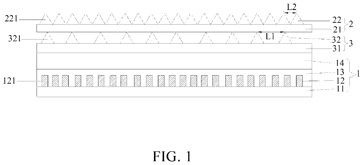
[0038]This embodiment provides a quantum dot light emitting diode (LED) backlight source. Please refer to FIG. 1, FIG. 1 is a structural schematic diagram of the quantum dot LED backlight source provided by this embodiment. The quantum dot LED backlight source includes a light source quantum dot diaphragm 1, a support diaphragm 3, and a prism sheet 2 which are disposed sequentially. The light source quantum dot diaphragm 1, the support diaphragm 3, and the prism sheet 2 are bonded together.

[0039]The light source quantum dot diaphragm 1 includes a flexible printed circuit board 11, a mini light emitting diode layer 12 disposed on the flexible printed circuit board 11, a quantum dot film layer 13 disposed on the mini light emitting diode layer 12, and a buffer layer 14 disposed on the quantum dot film layer 13. The buffer layer 14 have a function of blocking water and oxygen.

[0040]The mini light emitting diode layer 12 includes a plurality of mini light emitting di...

second embodiment

The Second Embodiment

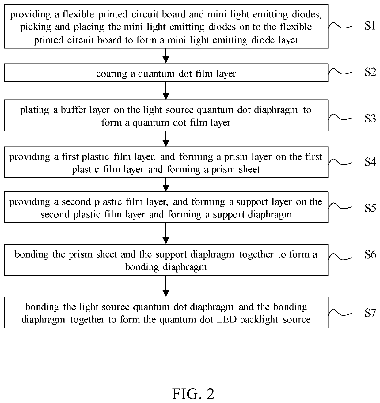
[0050]This embodiment provides a method for preparing the quantum dot LED backlight source related to the first embodiment. Please refer to FIG. 2, FIG. 2 is a flowchart of the preparation method for the quantum dot LED backlight source provided by this embodiment, which includes the following steps:

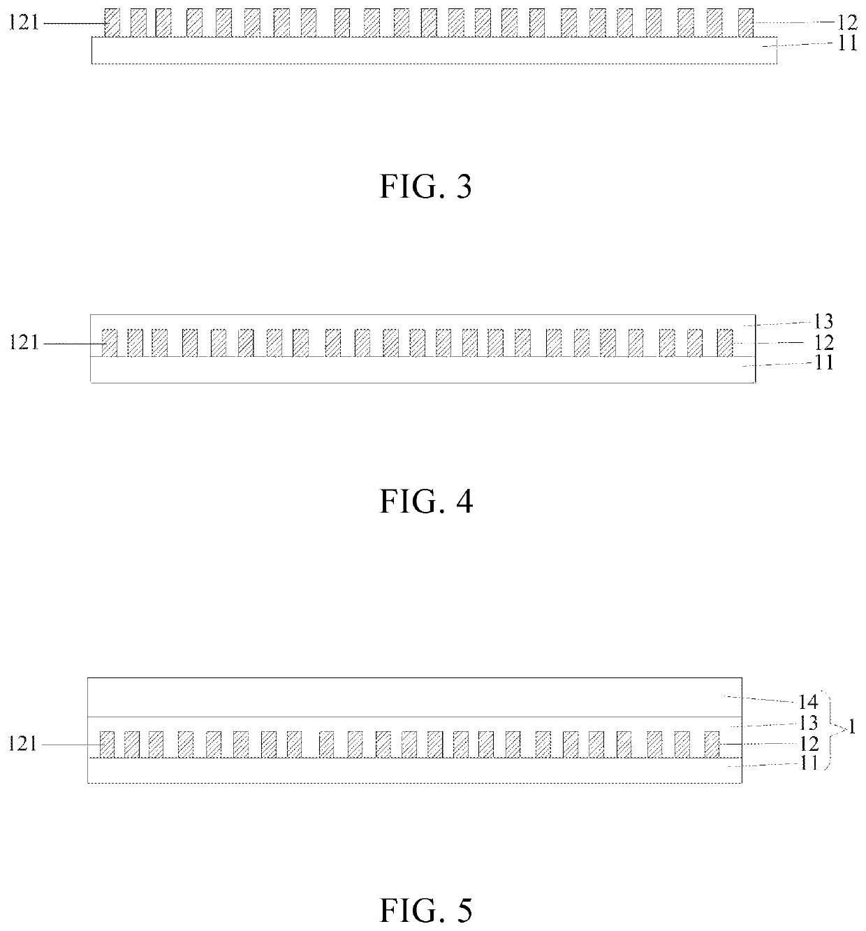
[0051]Step S1: providing a flexible printed circuit board 11 and mini light emitting diodes 121, picking and placing the mini light emitting diodes 121 on to the flexible printed circuit board 11 to form a mini light emitting diode layer 12.

[0052]Please refer to FIG. 3, FIG. 3 is a structural schematic diagram of the quantum dot LED backlight source of the step S1 in the preparation method provided by this embodiment.

[0053]Step S2: coating a quantum dot film layer 13.

[0054]Please refer to FIG. 4, FIG. 4 is a structural schematic diagram of the quantum dot LED backlight source of the step S2 in the preparation method provided by this embodiment.

[0055]The quantum dot f...


PUM

PropertyMeasurementUnit
sizeaaaaaaaaaa
flexibleaaaaaaaaaa
distanceaaaaaaaaaa

Abstract

A quantum dot light emitting diode (LED) backlight source which includes a light source quantum dot diaphragm, a support diaphragm, and a prism sheet which are disposed sequentially. The light source quantum dot diaphragm includes a flexible printed circuit board, a mini light emitting diode layer, and a quantum dot film layer which are disposed sequentially. The mini light emitting diode layer includes a plurality of mini light emitting diodes spaced apart, the quantum dot film layer and the mini light emitting diode layer are bonded together.

Description

FIELD OF INVENTION[0001]The present disclosure relates to a display panel technology field, and particular to a quantum dot light emitting diode (LED) backlight source and a preparation method thereof.BACKGROUND OF INVENTION[0002]Mini light emitting diodes (mini-LEDs) are chip products having a chip size less than 200 um. The market uses mini-LEDs as a backlight source for a liquid-crystal display (LCD) display, because it can realize ultra-thinness, multi-partition and is a product using small-size chips, which can match OLED products in display effect, and material cost of mini-LEDs has more competitive advantages than material cost of organic light emitting diodes (OLEDs), so that the mini-LEDs are proposed to be used.[0003]When mini-LEDs on the market are used as a backlight, they must be collocated with fluorescent powder to realize emittance of white light. In order to demonstrate a design requirement of a high-end model of mini-LEDs, generally a mini-LED product will be collo...

Claims


Application Information

Patent Timeline
Patent Type & Authority Patents(United States)
IPC IPC(8): G02F1/1335G02F1/13357
CPCG02F1/133607G02F1/133603G02F1/133606G02F1/133608G02F1/133614G02B5/045G02F2201/50
Inventor SONG, LIANYANQIU, YONGYUAN
Owner HUIZHOU CHINA STAR OPTOELECTRONICS TECHNOLOGY CO LTD
Learn More