
Mapping image display control device, method, and program

a control device and image technology, applied in image enhancement, instruments, applications, etc., can solve the problems of a catheter being likely to be erroneously inserted into a branch, difficult to use as an index for an assumed resection region,

Active Publication Date: 2022-04-19
FUJIFILM CORP
View PDF17 Cites 0 Cited by
  • Summary
  • Abstract
  • Description
  • Claims
  • Application Information

AI Technical Summary

Benefits of technology

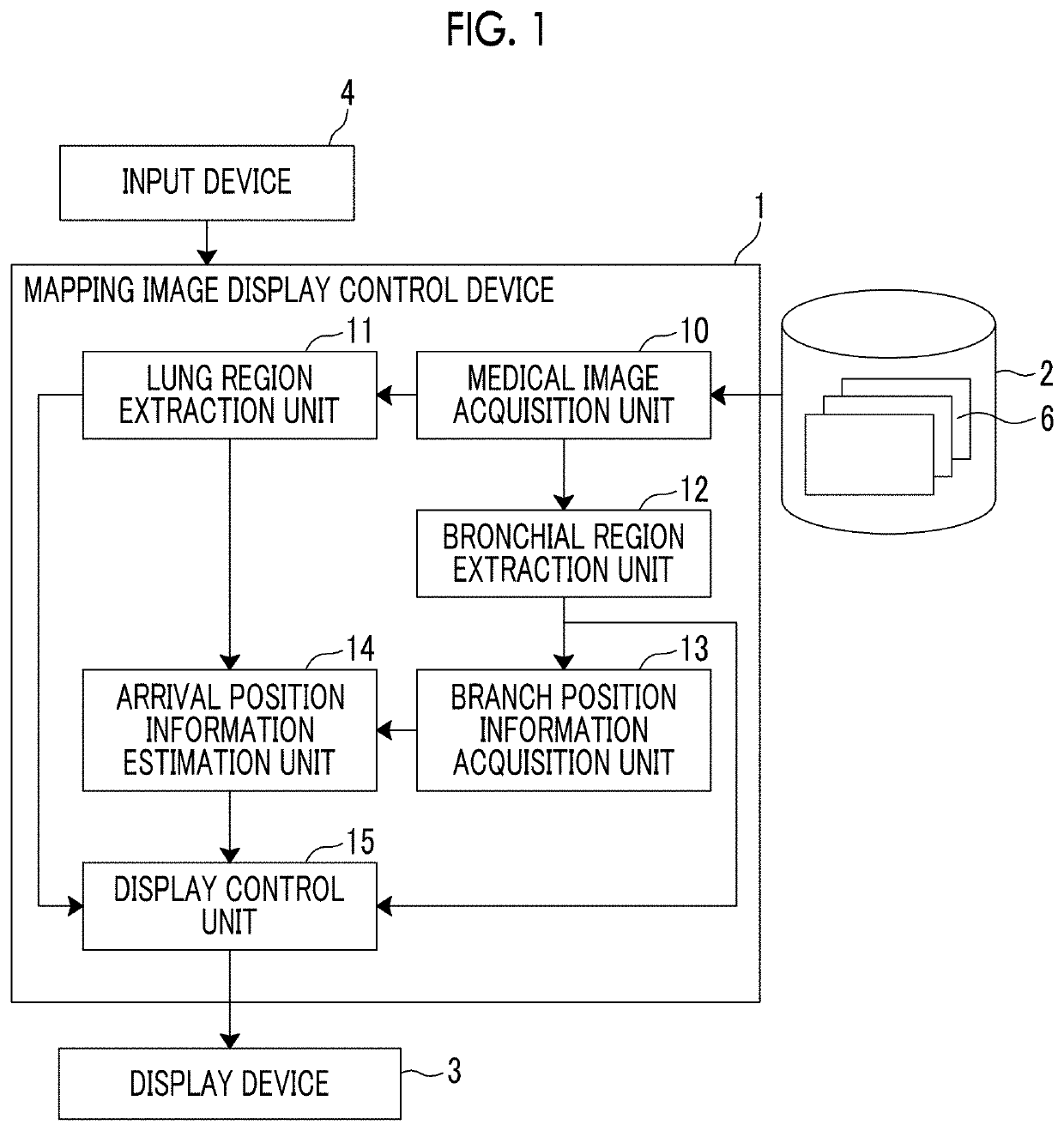
The present invention relates to a mapping image display control device and method for displaying a mapping image of a lung region. The device includes a lung region extraction unit, a bronchial region extraction unit, a branch position information acquisition unit, an arrival position information estimation unit, and a display control unit. The device can extract the lung region, bronchial region, and blood vessel region from a three-dimensional image and estimate the position of the bronchial region in relation to the lung region based on the information on the branch position. The device can also generate a mapping image by mapping the position of the bronchial region and the assumed mapping information to the surface of the lung region and display it on a display unit. The technical effect of the invention is to provide a more accurate and precise mapping image for the lung region that can help in the diagnosis and treatment of lung diseases.

Problems solved by technology

Therefore, a use as an index for an assumed resection region may be difficult, and in the worst case, it is necessary for the staining treatment to be performed again.
However, since a line-of-sight direction of an operator with respect to the X-ray fluoroscopic image is fixed, the catheter is likely to be erroneously inserted into a branch in a depth direction.

Method used


Image

  • Mapping image display control device, method, and program
  • Mapping image display control device, method, and program
  • Mapping image display control device, method, and program

Examples


first embodiment

[0043]Hereinafter, a medical image diagnosis support system using an embodiment of a mapping image display control device, method, and program of the present invention will be described in detail with reference to the drawings. FIG. 1 is a block diagram illustrating a schematic configuration of a medical image diagnosis support system according to the present invention.

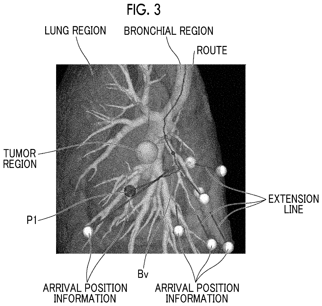
[0044]A medical image diagnosis support system of this embodiment performs support in a case where the VAL-MAP method described above is performed and, basically, simulates a position of a lung surface on which a dye is exuded in a case where the dye is sprayed onto a peripheral part of a bronchus, and generates and displays a mapping image obtained by mapping the position to the lung surface. By observing this mapping image, a doctor can recognize a position of the lung surface at which the dye is exuded in a case where the bronchus is selected and the dye is sprayed onto the peripheral part thereof, and therefore, a...

second embodiment

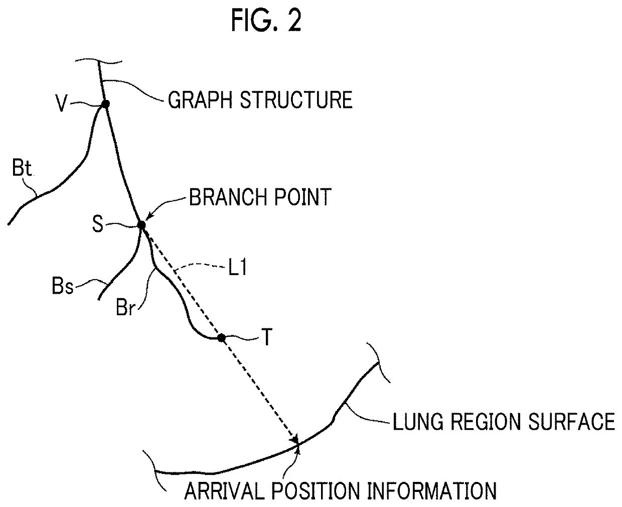
[0084]Therefore, the arrival position information estimation unit 14 of the second embodiment assumes bending of the bronchus as described above in consideration of a load on the branch, estimates a direction in which the peripheral branch extends during surgery, and estimates the assumed mapping information on the basis of the estimated direction.

[0085]Conditions of deformation (bending) of the bronchus in a case where the bronchoscope is inserted may be set, for example, for each peripheral branch in the bronchial region in advance, or deformation conditions may be set for each branch position of the bronchial region, a branch position present between the terminal of the specific peripheral branch and the proximal end portion of the bronchus may be specified in a case where a specific peripheral branch is selected, and the assumed mapping information may be estimated on the basis of the deformation condition of the specified branch position.

[0086]Specifically, the arrival position...


PUM


Abstract

An arrival position information estimation unit that estimates arrival position information at which an extension line of a peripheral branch included in a bronchial region arrives at a surface of a lung region, and estimates assumed mapping information other than the arrival position information of a specific peripheral branch on the basis of a preset condition in a case where the specific peripheral branch is set as a target branch, and a display control unit that generates a mapping image obtained by mapping the arrival position information of the specific peripheral branch and the assumed mapping information to a surface of the lung region and displays the mapping image on a display unit are included.

Description

CROSS-REFERENCE TO RELATED APPLICATION[0001]This application claims priority from Japanese Patent Application No. 2017-037061, filed on Feb. 28, 2017, the disclosure of which is incorporated by reference herein in its entirety.BACKGROUNDField of the Invention[0002]The present invention relates to a device, method, and program for simulating a position of a lung surface on which a dye is exuded in a case where the dye is sprayed onto a peripheral part of a bronchus, and generating and displaying a mapping image obtained by mapping the position to the lung surface.Related Art[0003]In recent years, a Virtual Assisted Lung Mapping (VAL-MAP) method has been proposed as a method of marking a resection region of a lung (see Masaaki Sato, and eight others, “Thoracoscopic wedge lung resection using virtual-assisted lung mapping”, [online], Jun. 12, 2014, Asian Cardiovascular and Thoracic Annals, <URL: http: / / aan.sagepub.com / content / early / 2014 / 06 / 12 / 0218492314539332>). In this VAL-MAP m...

Claims


Application Information

Patent Timeline
Patent Type & Authority Patents(United States)
IPC IPC(8): A61B34/00A61B5/08A61B5/00A61B6/00G06T7/11G06T7/187G06T17/00G06T19/20G06T7/00A61B34/10A61B34/20A61B17/00A61B5/05A61B6/03
CPCA61B34/25A61B5/004A61B5/08A61B5/4887A61B6/466A61B6/481A61B6/50A61B6/5217A61B34/10A61B34/20G06T7/0012G06T7/11G06T7/187G06T17/00G06T19/20A61B5/05A61B6/032A61B6/4405A61B2017/00809A61B2034/104A61B2034/105A61B2034/2057A61B2034/2065G06T2200/04G06T2207/10024G06T2207/10081G06T2207/10088G06T2207/30061G06T2207/30096
Inventor YAMADA, KENTA
Owner FUJIFILM CORP
Learn More