
Methods and systems for pipe wall thickness detection

a technology of pipe wall thickness and detection method, which is applied in the direction of analyzing solids using sonic/ultrasonic/infrasonic waves, instruments, heat measurement, etc., can solve the problems of pipework leakage, substantial safety, property and environmental risks, and pipework corrosion is one of the most widespread and costly problems, so as to avoid potential safety risks, preserve structural integrity of pipe, and facilitate mounting or dismounting

Active Publication Date: 2022-05-24
ZHEJIANG FUTURE TECH INST JIAXING
View PDF8 Cites 0 Cited by
  • Summary
  • Abstract
  • Description
  • Claims
  • Application Information

AI Technical Summary

Benefits of technology

This approach provides consistent and reliable pipe wall thickness measurements, avoiding safety risks and the need for expensive probes, enabling real-time monitoring of corrosion and preserving pipe structural integrity.

Problems solved by technology

Corrosion of pipework is one of the most widespread and costly problems in the petro-chemical, oil, gas, and power industries.
Wall-thickness loss due to corrosion along time may cause pipework leakage and pose substantial safety, property, and environmental risks.
When the temperature of pipework is elevated, such as in a refining plant, the corrosion damage is exacerbated.
The thin and long waveguide attenuates signal intensity, generates distortion of the waveform, produces unwanted clutter, and complicates data processing and high-resolution wall-thickness measurement.
Moreover, Lamb waves traveling inside a thin and long waveguide are sensitive and susceptible to environmental changes.
For instance, rainwater or oil stains on the surface of a waveguide may interfere with the propagation of Lamb waves.

Method used


Image

  • Methods and systems for pipe wall thickness detection
  • Methods and systems for pipe wall thickness detection
  • Methods and systems for pipe wall thickness detection

Examples


Embodiment Construction

[0028]Detailed description of the present invention is provided below along with figures and embodiments, which further clarifies the objectives, technical solutions, and advantages of the present invention. It is noted that schematic embodiments discussed herein are merely for illustrating the invention. The present invention is not limited to the embodiments disclosed.

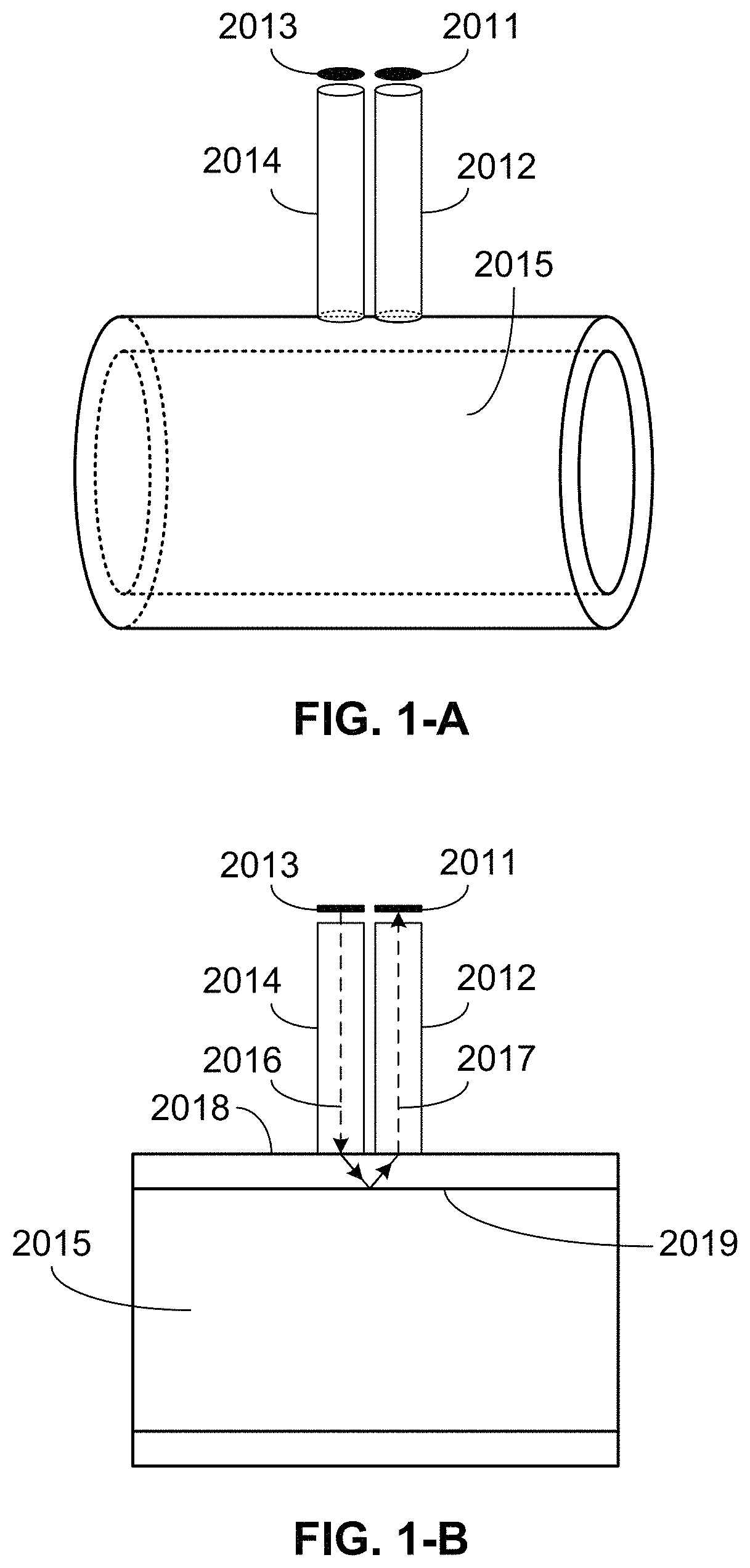
[0029]FIG. 1-A exemplarily illustrates a perspective view of an ultrasonic detection device, according to one embodiment of the present invention. The detection device comprises two ultrasonic waveguides 2012 and 2014 and two ultrasonic transducers 2011 and 2013. The waveguides may be elongated objects including right circular cylinders, semicircular cylinders, oval cylinders, square columns, rectangular strips, and so on. Ultrasonic transducers may be employed as an actuator to excite an ultrasonic wave signal or as a sensor to detect an ultrasonic wave signal.

[0030]Ultrasonic transducers may include piezoelectric t...


PUM

PropertyMeasurementUnit
diameteraaaaaaaaaa
diameteraaaaaaaaaa
diameteraaaaaaaaaa

Abstract

The present invention discloses ultrasonic nondestructive methods for pipe wall thickness measurement at high or low temperatures. An ultrasonic detection device comprises a first and a second ultrasonic waveguide. The waveguide length is selected according to the surface temperature of a pipe under inspection. A first piezoelectric plate causes generation of a plurality of ultrasonic excitation signals which is transmitted to the pipe through the first ultrasonic waveguide. The plurality of ultrasonic excitation signals has different group speeds when traveling along the first ultrasonic waveguide. The reflected ultrasonic wave signals are collected and transmitted to a second piezoelectric plate by the second ultrasonic waveguide. The pipe wall thickness is calculated using an ultrasonic wave signal which has the highest group speed. The first and second waveguides are arranged parallel and side by side. An isolation plate is disposed such that the first and second waveguides go through the plate perpendicularly.

Description

CROSS-REFERENCE TO RELATED APPLICATION[0001]This application claims priority to Chinese Patent Application No. 201910218226.1 filed on Mar. 21, 2019, the entire content of which is incorporated by reference herein.FIELD OF INVENTION[0002]This invention generally relates to ultrasonic nondestructive detection and specifically to ultrasonic nondestructive detection of pipe wall thickness.BACKGROUND OF THE INVENTION[0003]Corrosion of pipework is one of the most widespread and costly problems in the petro-chemical, oil, gas, and power industries. Wall-thickness loss due to corrosion along time may cause pipework leakage and pose substantial safety, property, and environmental risks. When the temperature of pipework is elevated, such as in a refining plant, the corrosion damage is exacerbated. Therefore, it is often required to examine pipe wall thickness regularly.[0004]Ultrasonic nondestructive detection is frequently used in pipework inspection. For applications at high or low tempera...

Claims


Application Information

Patent Timeline
Patent Type & Authority Patents(United States)
IPC IPC(8): G01N29/04G01N29/22G01N29/24G01N29/28G01K13/00G01N29/12G01B17/02G01N17/04G01N29/07
CPCG01N29/043G01B17/02G01K13/00G01N17/04G01N29/07G01N29/12G01N29/223G01N29/228G01N29/2437G01N29/2462G01N29/28G01N2291/011G01N2291/023G01N2291/02854G01N2291/102G01N2291/2698G01K1/143G01N29/38G01N2291/2634
Inventor LIU, SHUANGWENLIU, LEI
Owner ZHEJIANG FUTURE TECH INST JIAXING
Learn More